When debugging the switching power supply, in addition to measuring the voltage of the relevant component pins in the control circuit with a voltmeter, it is more important to observe the relevant voltage waveform with an oscilloscope to judge whether the switching power supply is in an optimal working state. This article focuses on the choice of oscilloscope test points. For example, when the test point is the output pin of the PWM control chip, the oscilloscope can simultaneously measure two important parameters of the amplitude and duty cycle of the drive pulse.
The choice of test points is very important. The test points are selected reasonably, which can ensure the safety of debugging and reflect the working state of the switching power supply, which can simplify the debugging process.
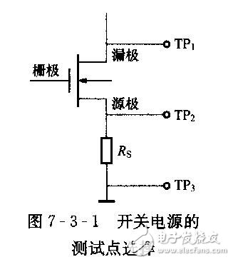
The test point selection of the switching power supply is shown in Figure 7-3-1. Test point TP1 is the drain of the MOSFET power switch tube, TP2 is the source of the switch tube, Rs is the current sampling resistor, and TP3 is the cathode of the primary primary high voltage loop. We can connect the two test points TP1 and TP2 to the two input channels (CH1 and CH2) of the dual trace oscilloscope and observe the voltage waveforms of the two points. At this time, the ground terminals of the two probes should be connected to the negative pole of the primary input DC loop at the same time, that is, the TP3 position. In actual measurement, the grounding clamp of the probe can be directly clamped to the grounding pin of the Rs.
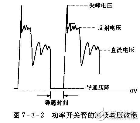
From TP1, you can see the drain voltage waveform of the power switch tube. This waveform can reflect the drain peak voltage, input DC high voltage, secondary reflection voltage, switching transistor turn-on voltage drop, and turn-on and turn-off time. In a single-ended flyback switching power supply, the drain voltage waveform of the power switch is shown in Figure 7-3-2.
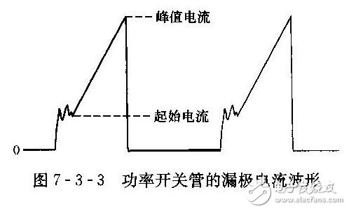
The source voltage waveform of the power switch tube can be seen from TP2. This waveform is the voltage waveform on the sampling resistor Rs, which can reflect the drain current and the on and off times. The drain current waveform of the power switch tube is shown in Figure 7-3-3. This waveform reflects the switching power supply operating in current continuous mode. During each cycle, when the switch is turned on, the drain current rises from the minimum starting current. The drain current reaches its maximum value before the switch is turned off.

The two test points TP1 and TP2 are critical and can basically reflect the working state of the switching power supply and whether there is any fault. Pay special attention to the waveforms of these two test points during the debugging process. When the input AC voltage is gradually increased, if the peak voltage or peak current is found to exceed the design range, the power should be turned off immediately to find the cause to prevent damage to the power switch tube.
Sometimes, in order to observe the current waveform of the primary winding of the high-frequency transformer, it is also possible to sample the resistor in series in the primary winding. The sampling circuit of the primary loop current is shown in Figure 7-3-4. The measurement status at this time is the "floating" measurement mentioned in the previous article. In theory, the sampling resistor can be connected in series at the upper or lower end of the primary primary winding; in fact, if it is connected in series at the lower end of the primary winding, see the Rs1 position in the figure, a floating high-voltage pulse is generated on the oscilloscope ground line during the measurement. This is not safe, it also produces large measurement interference and errors, and may also affect the normal operation of the switching power supply. The correct method is to connect the sampling resistor in series with the upper end of the primary winding, see the Rs position, and connect the signal line of the oscilloscope probe to the TP1 end and the grounding clamp of the probe to the TP2 end. Thus, although the primary loop circuit waveform is reverse polarity, the interference and error during measurement are minimal, and have no effect on the normal operation of the switching power supply. The positive current waveform can be viewed through the oscilloscope's reverse polarity (INV) function button.
Special Note: When observing the primary current waveform of the high-frequency transformer, the grounding clamp of the oscilloscope probe will be connected to the positive terminal of the DC high voltage. The probe and ground clip of other channels of the oscilloscope must be disconnected from the relevant circuit, otherwise short circuit or damage to the circuit components will occur. That is to say, when observing the primary primary loop current waveform, only one channel can be used, and the other channels must be completely disconnected. This problem does not exist when using an oscilloscope with built-in isolation channel technology.
KNM5 Series Moulded Case Circuit Breaker
KNM5 series Moulded Case Circuit Breaker is MCCB , How to select good Molded Case Circuit Breaker suppliers? Korlen electric is your first choice. All moulded Case Circuit Breakers pass the CE.CB.SEMKO.SIRIM etc. Certificates.
Moulded Case Circuit Breaker /MCCB can be used to distribute electric power and protect power equipment against overload and short-current, and can change the circuit and start motor infrequently. The application of Moulded Case Circuit Breaker /MCCB is industrial.
Korlen electric also provide Miniature Circuit Breaker /MCB. Residual Current Circuit Breaker /RCCB. RCBO. Led light and so on .
KNM5 series Molded Case Circuit Breaker,Small Size Molded Case Circuit Breaker,Electrical Molded Case Circuit Breaker,Automatic Molded Case Circuit Breaker
Wenzhou Korlen Electric Appliances Co., Ltd. , https://www.zjmannualmotorstarter.com