Application Practices on the Design of Power Supply System in Outdoor Lighting System Liu Shuilong, Shashan Coal and Electricity Group Corporation, Xiqu Mine, Taiyuan 030002, China) Selection of power supply lines, selection of power supply system standards, and new control methods in lighting systems.
―01―06 Author Liu Shuilong male 38-year-old engineer 01: A common lighting design is the lighting of roads, squares, open-air goods, etc. The function is to ensure the safety of people in the dark, to meet the normal outdoor activities and work. Claim. There are many contents involved in outdoor lighting design, the most important of which is the power supply and distribution system. Due to the different uses of outdoor lighting and different places, the design content should be different.
1 power supply line due to low-voltage power supply has the advantages of small engineering volume and low investment. At present, most of the street lamps in China use low-voltage power supply. According to China's power supply situation and the use requirements of different places, the national regulations have stipulated the voltage deviation of the lighting power supply. In order to ensure the life of the light source, the terminal voltage of the street lamp must not exceed 105% of its rated voltage. In the industrial enterprise lighting design standard GB5003492, the requirements for industrial and mining enterprises' roads are that the voltage is not less than 90% of the rated value. The urban road lighting is based on the requirements of urban road lighting design standard G4591, from the reliability of power supply and energy saving. From the perspective of the point of view, it is advisable to use 10KV distribution line to connect the special transformer for road lighting, the optimal load factor is 70%, the end voltage requirement of the lighting line is the same as above; for the road lighting line powered from the common transformer, the terminal voltage It must not be lower than 95% of the rated value. Therefore, when designing road lighting supply and distribution lines, the voltage loss calculation of the line should be carried out according to different technical conditions, so that the power supply and distribution network has certain conditions under the premise of meeting the plan. The redundancy, the terminal voltage meets the above requirements, and the line section is economically reasonable.
With the development of economic construction, the use of underground direct buried cables for road lighting has been the most common laying method. The advantages of direct distribution of distribution lines are obvious, high heat dissipation, high current carrying capacity, and parallel distribution capacitance between the cores of the cable. On the line. It can improve the natural power factor without being affected by the climate, reduce the damage of external forces, and improve the reliability of power supply. In addition, buried cables help the environment to be more aesthetically pleasing. Therefore, the national regulations stipulate the use of underground cables to power road lighting in the case of technical and economic conditions. In addition, from the perspective of energy saving, road lighting fixtures use more gas discharge lamps, and the neutral line section of the three-phase four-wire power supply line should be selected according to the maximum one-phase current.
In the actual design process, the common load torque table for the verification of the street lamp line is simplified. The load torque table in the current design manual lists fewer cases of direct cable burying, especially the cross-linked cable widely used in recent years. Compared with other lines, the price of the cable is relatively high. Therefore, it is particularly important to select a reasonable cable type. In the power supply network of road lighting, the street lamp load is spaced at a certain distance and is substantially evenly distributed on the line, for its end. The voltage drop is obviously not accurate enough to be calculated by the load torque meter, and the computer's analysis and calculation of the lighting distribution network can quickly and quickly check the voltage loss at the end of the line according to different environmental conditions. If a high-intensity discharge lamp is used, the voltage loss value of the line should also be checked according to the starting and restart characteristics. So, for the distribution of road lighting. Especially for the end load far from the power supply, after determining the specific line and laying method, the necessary analysis and calculation should be carried out in combination with the environmental conditions to optimize the design of the road lighting power supply and distribution line to ensure the reliability of the power supply and the service life of the lamp.
2 line practice protection measures Because of the vulnerability to outdoor open air environment factors such as day and night temperature difference, wind blowing and sun and rain, road lighting devices and lines are prone to failure, so limit the fault range. National regulations require that each street light be equipped with a separate fuse protection, and the corresponding protection should be installed on the power supply line. The general requirements for distribution lines in the design specification of low-voltage power distribution GB50054 95 are short-circuit protection and load protection. Outdoor lighting lines do not require overload protection. However, overload protection should be installed for lines in explosion and fire hazard areas. To prevent excessive temperature rise due to insulation failure.
The current national regulations have gradually been consistent with the IEC standards, so the requirements for preventing direct and indirect contact with electrical installations are more stringent. In addition to short-circuit and overload protection to ensure the safety of lighting equipment, in order to protect the safety of personnel, ground fault protection should also be adopted. Ground fault refers to the short circuit between phase-to-ground or ground-connected conductors. For cable circuits laid underground, it is common to damage the electrical insulation, resulting in phase and PE/PEN lines, exposed conductive parts and A short circuit occurs between the earth, a short circuit occurs between the conductive part of the street lamp and the earth, and a fault voltage is formed between the conductive part of the street lamp and the ground or other grounded conductive part, causing the electric shock or sparking of the person to cause a fire or explosion. . Measures to prevent such accidents are: shortening the time to cut off the fault and reducing the expected contact voltage. The former is accomplished by the correct selection and setting of line protection appliances, while the latter is achieved by grounding and equipotential bonding of exposed conductive parts of adjacent equipment. Since the ground fault protection is more complicated, and the protection mode is related to the grounding form and the fault loop impedance, the following is a description of the ground fault protection measures and setting and setting of the power supply and distribution lines according to the commonly used TN grounding system for road lighting in different occasions.
Since the special protection line PE is set between the power supply point and the street lamp, the exposed conductive part is required to be electrically connected with it, and the ground potential of the phase zero short circuit or the neutral line potential offset is not reflected on the PE line, and the ground fault protection is set. The purpose is mainly to prevent the insulation damage of the underground cable line, usually by the overcurrent protection of the protective device, but the sensitivity is not high, it should be verified according to the following formula: R fault current is exposed between the conductive part and the power point through the street lamp The resulting voltage drop causes the resistance of a line of contact voltage.
I. When the above-mentioned requirements are not met, the national regulations are based on the existing technical level and economic conditions in China. It is stipulated that if the zero-sequence protection sensitivity is sufficient, the protection setting can be adopted. Need to avoid the unbalanced current of the line. Since the zero-sequence protection is not sensitive enough compared to the leakage protection, the IEC standard is also included, so the leakage protection is most effective.
For urban road lighting systems. Because the distribution line is long and the cross section is small, the ground fault current is often insufficient to make the overcurrent protection action. In addition to the lack of professional operation and maintenance management, it is most feasible to set the leakage protection at the power point. The priority value of the leakage protection non-action value is the rated action current. 1 The ice should be greater than the normal operation. The line and street lamp leakage current can be estimated at 22 mA/km. The two-phase cable line is equal to the supply voltage balance and the three relative distribution capacitances. The leakage current is close to zero, but in actual operation, the system voltage cannot be completely balanced, the distributed capacitance of each phase is not equal, and there is an asymmetric operation. Therefore, the three-phase cable can still be considered at 22 mA/km. The street lamp can be calculated according to 1 mA/set. Therefore, the normal leakage current of road lighting is usually greater than 30 mA level, which prevents direct contact with the leakage protection value of the personnel. The general installation height of the street lamp facility can prevent direct contact, thus, leakage Protected 1N=500mA, but should not use its upper limit. The best protection is achieved by leakage protection of 1N=300mA. Therefore, according to the general requirements of residual current operated protector, GB6829-95, the rated leakage current is given priority. Value requirement, 1AN=300mA is more reasonable.
For the road lighting of industrial and mining enterprises, it is usually a transformer with other loads. According to the ground fault current value and line type at the low-voltage side outlet of the transformer provided in the design manual, the allowable line length when using over-current protection and ground fault protection can be calculated. If the actual length of a line is greater than the calculated value, set 1 leakage protection of ice = 300 mA; the line within the allowable length does not need to be installed.
For the road lighting of residential buildings, shopping malls, hotels and other civil buildings, there are more garden lights and lawn lights, and the distribution lines are relatively short. From the perspective of user safety, it is recommended to set the leakage protection of lAN=300mA to prevent direct contact with electricity. .
―C system, the protection line is in common with the neutral line, and the external part of the street lamp must be directly connected to the PEN line, that is, the PE line and the N line of the lighting device are independently connected to the PEC line. Road lighting is mainly based on single-phase load, and adopts three-phase four-wire power supply. When the PEN line breaks, the exposed part of the street lamp has a phase voltage of 220V, and the fault is difficult to find in time. Therefore, the danger is added. According to foreign experience, it can only improve the mechanical strength of the PEN line and strengthen the protection measures. To overcome, IEC/TC64 has strict requirements for reducing the cross section of PEN line. It is stipulated that only when concentric cable is used and PEN wire terminal is double connected, it is allowed to reduce the cross section of PEN line, but not less than 4mm2. Install ground fault protection device Only the phase line can be disconnected, that is, only the three-stage/unipolar switch can be installed, and the phase-zero short circuit of the line also turns into the ground fault. After the protection action, the fault type is difficult to judge. When the phase-zero short-circuit or neutral potential shift occurs, the potential of the exposed conductive part of the street lamp rises, which may lead to the danger of contact between the maintenance personnel. Therefore, foreign regulations have not allowed the power supply and distribution in the TN-C system. Ground fault current protection is set on the line.
Therefore, for lighting lines with a line length within a small range, a TN-C grounding system can be used without leakage protection. Urban road lighting usually has a long line. It is recommended to adopt TN-S system. The length of road lighting line of industrial and mining enterprises exceeds a certain range. The grounding adopts TN-S system. The protection requirements are as mentioned above. It should be noted that if the line is exploding In the danger zone 1 or the fire danger zone 10, only the TNS system can be used to set the leakage protection of 1=300 mA; while the residential buildings, shopping malls, hotels and other civil buildings have relatively short road lighting, and can pass appropriate large lines. The cross-section improves the single-phase ground fault current value, which usually meets the requirements of over-current protection and ground fault protection. However, considering the low installation height of this type of lighting and neglecting maintenance management during operation, it is recommended to use TN-S system to set up lAN. =300mA leakage protection.
It should be emphasized that the ground fault protection ground protection appliance automatically cuts off the fault circuit to meet the protection requirements. Except for the quality of the protection appliance itself, any error in the design, construction and maintenance management work may lead to protection failure and leakage protector action. Sensitive, but also the possibility of misoperation, refusal and failure, so this type of protection is not a reliable electrical safety measure, and can not prevent the intrusion of external dangerous voltage. When there is a low-voltage overhead power line in the road lighting outlet, a lightning arrester should be installed on the phase line of the TNS system, the neutral line of the neutral line and the TNC system. Therefore, various safety measures should be combined and used to achieve maximum safety.
3 control system street lamp control mainly uses photoelectric control and quartz clock, time switch control, the former has the possibility of misoperation, and then adjust the time with the season. The new street lamp control relay can meet the control requirements of road lighting. The input terminal has switching quantity and analog quantity, and the output circuit is 4-12. It can contact 4 to 12 three-phase/single-phase street light circuit according to photoelectric signal. The device can be controlled according to its internal clock and four timer output loops, and the operation mode is extremely flexible. The control relay has strong anti-interference ability and small volume, and can be installed in the distribution box. The external wiring is simple and the control logic can be directly modified on the liquid crystal display of the relay. For road lighting control, it is a simple, economical and reliable method.
In summary, China's electrical standard specifications are gradually in line with TEC standards, but there are still problems such as imperfect content, low safety level, and inconsistent standard specifications. In the design of power supply and distribution systems, in addition to strictly complying with the requirements of the regulations In addition, according to the specific conditions of road lighting, electrical safety and investment savings should be considered in order to make the most reasonable design.
Jinghongyi PCB: PCBA, PCB Assembly , Printed Circuit Board Assembly Services Provider.
Jinghongyi PCB is a leading PCB manufacturer and assembler in China. It provides one-stop PCB Manufacturing and PCB assembly services, including PCB Prototype manufacturing, small and medium batch manufacturing, and Prototype PCB Assembly Services, Quick Turn PCB Assembly, Low Volume & Small Batch PCB Assembly, Middle Volume PCB Assembly, High Volume PCB Assembly, Turnkey PCB Assembly Service (including PCB production, component procurement, assembly, quality management, etc.), Lead Free PCB Assembly, Multilayer PCB Assembly, LED Lighting PCB Assembly with High Quality, Reasonable Price and Fast Turnover Time Ability.
What Does PCB Assembly Mean?
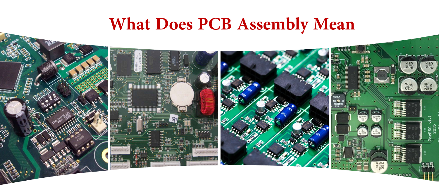
PCB Assembly Service in China

Although there are many companies in the United States, Britain, India, Australia, Canada, Mexico, Taiwan, Malaysia, Thailand, Germany, Romania and other local selection of PCB assembly manufacturers, but they are not cheaper than assemble in China, because China's PCB assembly cost is lower, better quality.
Why Choose US for PCB Assembly Services - Turnkey, Quickturn PCB Assembly Service

|
Turnkey Services |
Instant Online Quote |
Affordable Pricing |
|
Contact our online customer service or send us an email.
We offer 7*24 hours of online real-time quotation and online customer support. |
We have many years and rich experience in PCB production and assembly. There are very professional technicians and operators, with very advanced PCB assembly process, they are the guarantee of product quality. On this basis, we can also provide you with cheaper, better quality products. |
|
Quick-Turn assembly |
100% Quality Guarantee |
Mature Capabilities |
|
Get the entire PCBA produced in 20 working days from order confirmation to dispatch, including sourcing of parts. However, if you need faster delivery time, we can do it, but you may need to pay an additional premium. |
100% quality guaranteed - free re-work if needed. All parts are sourced from reliable suppliers, and each board undergoes free visual inspection. X-ray inspection, AOI testing, In-Circuit Testing (ICT), and functional testing are also available. |
JHYPCB's assembly lines are fully compliant with IPC-A-610F, are capable of SMT, through-hole and mixed assembly, and can solder BGA and fine-pitch components from 0.38mm pitch. PCB types include rigid, flexible, rigid-flex and aluminum boards. |
|
Prototype, Small or Large Batch |
Sourcing Options |
Considerate Customer Service |
|
Whether you need prototype PCB assembly or bulk assembly, JHYPCB can cater for as little as a single piece 1 to 10000 pieces and has dedicated assembly lines for both low and high volume needs. |
We can source components from reputable distributors, or you can choose from us. These parts are cheaper and can reduce the entire PCBA production time to 7 working days. |
Every PCBA order is assigned a project manager to assist you with the order process. The engineering and assembly teams will also communicate any issues with you to ensure your order proceeds as planned. |
PCB Assembly Capabilities

-
Prototype PCB Assembly as Quick as 1 Day
Our printed circuit board assembly service is China's leading one-stop solution for PCB and assembly under one roof; specializing in small and medium runs with fast lead-times and no minimum quantity requirements.
-
A Seamless Process from PCB fabrication to PCB Assembly
All printed circuit boards assembled by JHYPCB are maded and we maintain full control of the entire process so you don't have to manage multiple vendors. When you choose JHYPCB, you can be sure that your PCBs flow directly into our in-house Assembly Department to begin assembly without delay.
-
Assembly Types
-
Surface Mount (SMT) Assembly
We are capable of small volume SMT prototyping PCBs with both automated and manual assembly.
-
Ball-Grid-Array (BGA) Assembly
We are equipped with advanced automated BGA placement equipments as well as X-ray inspection equipments to guarantee the quality of BGA assembly.
-
Through-Hole Assembly
Components are placed by inserting leads into holes that covered with solder. Both automated and manual through-hole assembly are available.
-
Mixed Assembly
Both SMT and Through-Hole components will be placed on the PCBs. Single or double side mixed assembly is available.
-
Kit Assembly
PCB Types for Assembly
- Prototype PCB Board
- FR4/ Rigid PCB Board
- Aluminum PCB Board
- LED PCB Board
- Flexible PCB Board
- Rigid Flex PCB Board
- Solder Types
Lead-Free (RoHS compliant)
- Assembly Time
From 8 hours to 72 hours once all parts are ready
- Component Types
- Ball-Grid-Arrays (BGA) of 0.25mm pitch with x-ray testing
- Passive components as small as 01005 (0402) package
- Fine-pitch components as small as 0.38mm pitch
- Test Types
- Visual Inspection
- X-Ray Inspection
- AOI Testing
- In-Circuit Test
- Functional test
- Component Suppliers
- More than 10,000 in-stock components (OPL)
- Digikey, Mouser, TME, Element 14 and more-
- PCB Assembly Testing Capabilities Learn More
| Category | Product Function | Test Type | Test Location |
|---|---|---|---|
| MCU |
51 serial MCU AVR serial MCU ARM Cortex M0, M0+, M3 and M4 serial |
IC Programming | JHYPCB's Fab |
| General |
GPIO Functional Testing Voltage, Electricity Current, Resistance Test, etc. I2C/Uart/SPI/CAN/One Wire/SWD Temperature, Humidity, Atmospheric Pressure etc. ... |
Functional Test | JHYPCB's Fab |
| Communication |
GSM/WCDMA/LTE GNSS Bluetooth/LE Ethernet NFC 802.11/b/g/n/a/ac ZigBee Sub-1 GHz 315/433/868/915 |
Functional Test | JHYPCB's Fab |
| Monoboard Computer | BeagleBone, Raspberry Pi, etc. | Functional Test | JHYPCB's Fab |
| Certification | FCC, CE, GS, TELEC etc. | Regulatory | Accredited Third-Party Lab |
PCB Assembly Applications
 |
 |
 |
 |
|
Aerospace |
Automotive |
Biomedical |
Consumer-electronics |
 |
 |
 |
 |
|
Energy |
Industrial |
Network-computer |
Telecommunications |
PCB Assembly Manufacturing Design Tips

-
Choosing between ROHS (LEAD-FREE) or standard (LEADED) solder
RoHS is used most frequently when shipping to Europe. As RoHS and Leaded solder temperatures are different, boards must either be completely soldered with RoHS or Lead. This includes BGAs. Non-RoHS components can withstand RoHS process. Avoid mixed process; that is, mixed solder. For example, a standard HASL bare board should not use a RoHS assembly process.
-
Water Clean
Aqueous clean process uses water soluble flux during soldering. The board is cleaned using water. This process yields shinier solder joints and an overall cleaner looking PCBA, without any flux residue.Use No Clean Flux only if your PCBA has some parts (batteries, microphones, speakers, relays, etc...) that can be damaged if submerged in a water wash. No Clean Flux leaves flux residue on the finished PCBA; however, flux is non-corrosive and non-conductive.
If a few components are water sensitive, you may choose to have the PCBAs processed with water soluble flux without initially soldering the water sensitive components. Make sure include specific instructions to hand solder these few components after cleaning with No Clean Flux.
-
Silkscreen
-
Placement (X-Y) Centroid Files
If you do not send centroid files with you CAD data, we can extract them for an extra fee.
-
Shortages
-
Fiducial
-
Moisture Procedure
-
Paste Layers
-
Multi-part Assembly orders
-
Substitutions
PCB Assembly Cost

PCB Assembly Cost = PCB manufacturing cost + PCB frame test or flying probe test fees + PCB engineering cost (only for small prototype order) + Component cost (additional 5%) + SMT assembly charges + PCB assembly test cost + Box building charges + Package cost (for special application) + Logistics cost (requested)
PCB Assembly Process

PCB Assembly Process
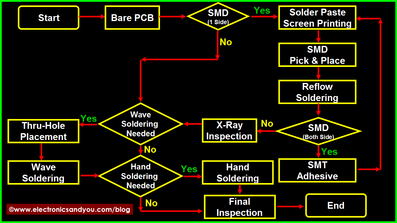
PCB Assembly Process Flow Chart
Things Needed for Printed Circuit Board Assembly
Following electronics parts and consumables are needed for PCB assembly
- Printed Circuit Board
- Electronic components
- Soldering materials including solder wire, solder paste, solder bar, solder preforms (depending on the type of soldering to be done)
- Soldering flux
- Soldering equipment including soldering station, wave soldering machine, SMT equipment, inspection and testing equipment etc.
Once all of the above equipment, electronic parts and all raw materials are arranged, it is time to start the printed circuit board assembly process.
1. PCB Manufacturing
PCB design & fabrication helps you with experienced PCB design and fabrication, high accuracy, quality control. In general, your PCB prototype can be well served by us. PCB Assembly includes layout, fabrication and assembly. We also have monthly abilities of offering 35,000 square meters PCB, 80 million point SMT and introduce ICT, flying probe, AOI, X-ray, function test, burn-in test into inspection phase. We can help you with a system of transforming natural resources, raw materials and components into a finished product that is delivered to the end customer and strive to have the most optimized supply chain to make efficient and costs lower.
2. Screen Printing of Solder Paste onto PCB Board
loctite solder pastePhysicochemical and process property of solder paste directly impact SMT soldering quality. Solder paste printing is applicable for placing appropriate amount solder paste onto PCB pads, in order to ensure good circuit connection between SMT components and PCB pads and their mechanical strength. Solder paste printing is the critical process of SMT. Metal template printing is conventionally applied so far. According to related statistics, 60%~70% quality problems are caused by solder paste printing in premise of quality guarantee of components and printed circuit board. Requirements of solder paste printing:
a. Place solder paste appropriately, evenly and uniformly. Solder paste shape is clear and neighbor shapes do not connect. Solder paste shape is in compliance with that of pad, without any dislocation.
b. In general, the unit area solder paste amount should be 0.8mg/mm2, particularly 0.5mg/mm2 for narrow-pitch components.
c. After solder paste printing, the shape has no heavy collapse and edges are trim. Plate surface is not allowed to be contaminated by solder paste.
There are a large variety of solder paste with different alloy compositions, granularity and viscosity even for all from one manufacturer. How to choose appropriate solder paste highly impacts the product quality and cost. Now NOD Electronics is using Loctite lead free solder paste. We have figured out Loctite solder paste is reliable to ensure good product quality after process engineering test of its printability, demoulding, thixotropy, cohesiveness, wettability, welding spot defect and residue.
3. Lead-free PCB Assembly
In light of environmental concerns and customer request, we can offer lead-free PCB board assembly which complies with RoHS standards. At upstream, we choose PCB laminates in compliance with RoHS standards for PCB manufacturing. Also we use lead free solder paste and related reflow/wave ovens. We strictly fulfill RoHS requirements in light of your local regulations and don`t want to make you into any trouble on this basis.
4. Burning Program and In-Circuit Test (ICT)
Our test engineers will check short circuit, voltage, current, signal transmission of PCB assembly boards according to your ICT test plan. A professional report will be handed up to you if for any detected problems. For batch order, we design exclusive test frames to fast the ICT test process. We are also well sophisticated with decoding and burning program for you. Related test frame will be built to ensure products work effectively according to your requirements.
PCB Assembly Requirement List
| No. | Types Of Assembly | File Format | Component Footprinr | Component Package | Testing Produres | Produres | Others |
| 1 | SMT ASSEMBLY | Gerber RS-274X | 0201,0402,0603- | Reels Package | Visual Inspection | Lead-Free(Rohs) | Custom Reflow Profile |
| 2 | SMT & THT Assembly | BOM(.xls,.csv,.xlsx) | BGA,QFN,QFP,PLCC | Cut Tape Package | X-Ray Inspection | Leaded Solder | Standard Reflow Profile |
| 3 | 2 sided STM,THT Assembly | Pick-N-Place/XY file | SOIC,POP...Connectors | Tube and Tray | AOI,ICT(In-Circuit Test) | Reflow Soldering | Smallest Size:0.2"x0.2" |
| 4 | Mixed Assembly | - - | Small Pitch of 8 Mils | Loose parts and bulk | Functional Testing | Wave Soldering | Largest Size:15"x"20 |
Find Out More
Flexible PCB Circuit Board Assembly
Through Hole Technology Assembly
Mixed Technology PCB Assembly
Double Sided PCB Assembly
Learn More Information
How to Mixed Technology PCB Assembly
Comparison between THT Assembly and SMT Assembly
How to start to Prototype PCB Assembly
Introduction About Single-sided and Double-sided SMT Assembly
How to ensure a smooth PCB assembly
How to Reduce PCB Assembly Cost
PCB Assembly Service
Printed Circuit Board Assembly, PCB Assembly Service, PCB Assembly
JingHongYi PCB (HK) Co., Limited , https://www.pcbjhy.com