First, the instrument introduction
Each car is equipped with a certain number of car instruments. The number and type of these electronic instruments vary greatly from model to vehicle and from generation to generation. A variety of meters, indicators and alarms are indispensable parts for the driver to understand the state of the car. Automotive electronic instruments reflect the operational status of the various parts of the car and the useful information of various systems on the car. The electronic instrumentation of the car provides a guarantee for the driver to use the car correctly and drive safely.
Traditional automotive instruments are mechanical or electromechanical. They are simulated by hands and scales. These instruments have the disadvantages of less information, lower accuracy, larger size, poor reliability, and poor visual characteristics. It also makes the driver fatigued and can't satisfy people's pursuit of car comfort and convenience. After entering the 1960s, people began to develop automotive electronic instruments, but the electronic components at that time did not reach the level required for automotive use. Until the late 1970s, with the advancement of semiconductor technology and display component technology, automotive electronic instruments Finally came out. With the advancement of electronic technology, the emergence of new sensors and new electronic display devices, automotive electronic instruments have developed rapidly. The use of microcomputer-driven electronic instrumentation systems in modern automobiles is becoming increasingly popular. The microcomputer-driven dashboard uses a microcomputer to process information from the sensor and direct the meter display.
Hyundai's instrument panel assembly is generally divided into two parts, one for the dashboard and the instrument panel and the platform in front of the steering wheel, and the other for the sub-dash on the driver's side channel. The instrument panel is the main body of the installation indicator. It collects the monitoring instruments of the whole vehicle. It reveals the engine speed, oil pressure, water temperature and fuel reserves, the working status of the lights and generators, the current speed and mileage of the vehicle, etc. . Some dashboards also display information such as shift gears, clocks, ambient temperature inside and outside the vehicle, road tilt and ground height. Most modern cars are equipped with control components for air conditioners, audio equipment, etc. on the sub-dashboard, which makes the overall layout compact and reasonable, and also facilitates the driver's operation [23]. With the development of the modern automobile industry and electronic technology, various systems and institutions in automobiles have become increasingly complex, and the amount of information on the driving of automobiles and various working conditions has increased remarkably. At the same time, in order to improve the environmental protection, safety, economy and intelligence of automobiles, car drivers need more and more rapid understanding of various information about car operation, which makes car electronic instruments develop to information display centers. An important part of the driver information system. The replacement of traditional mechanical or electromechanical analog instruments by automotive electronic meters has become a trend of development.
The use of electronic display technology, that is, the thin flat electronic display technology, the car's flat panel displays the numbers and information. It is very clear. It replaces the analog display speed and engine tachometer used in the past, so that the driver can drive. At the same time, changes in meter numbers and other information can still be clearly seen. It has the advantages of fast test response, accurate indication, flexible graphic design, clear digital, good visual performance, high degree of integration, high reliability and low power consumption.
Since there are no moving parts, the reaction is fast, the reliability is good, the arrangement is flexible and compact, and the best display form is available. Generally, in addition to requiring the automobile instrument to be durable, vibration-proof, accurate in indication, convenient in reading, and less affected by temperature and humidity, it is also required to be light, comfortable, beautiful and have good interchangeability. Automotive electronic meters meet these requirements.
At present, electronic instrument panels use electronic display devices and high-voltage driver integrated circuits and other technologies, and some use all-digital integrated circuits, which not only improve the test accuracy, but also input digital information into the car microcomputer to realize the data of parameters such as vehicle speed and mileage. Analysis and calculations give the car more control. The tachometer, voltmeter, fuel gauge, oil pressure gauge and water temperature gauge are linear integrated circuits, which are convenient for matching various electronic sensor components.
Automotive electronic instrumentation will become an intelligent system that integrates the functions of sensory, identification, analysis, information base, adaptation and control, providing vehicle driving information and ensuring safe driving.
1, water temperature gauge
The water temperature gauge is used to display the operating temperature of the engine cooling water. Commonly used are electrothermal and electromagnetic. Among them, the electrothermal water temperature meter and the electrothermal oil pressure gauge structure work similarly. The structure and principle of the electromagnetic water temperature meter are shown in Figure 3-4.
1) Structure
It consists of a thermistor sensor installed in the water jacket of the cylinder head and a water temperature display meter mounted on the instrument panel. The sensor consists of a housing, a terminal block, and a negative temperature coefficient thermistor (some models use a positive temperature coefficient thermistor). The water temperature display is composed of a plastic bracket, two series coils L1, L2, and an armature with a pointer.
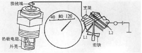
Figure 1 Electromagnetic water temperature gauge structure
2) Working principle
When the power switch is turned on, the current consists of the battery positive → pole ignition switch → coil L1 → two ways (one through the thermistor; the other through the coil L2) → grounding → battery negative pole to form a loop.
When the water temperature is low, the resistance of the thermistor in the sensor is large. After the current passes through L1, most of it flows into L2, and the resultant synthetic magnetic field causes the armature with the pointer to deflect to the left, so that the hands point to the low temperature scale; when the water temperature is high The resistance of the thermistor in the sensor is reduced, and the current in L2 is relatively reduced. The resulting synthetic magnetic field causes the armature with the pointer to deflect to the right, so that the hands point to the high temperature scale.
2, fuel gauge
The fuel gauge is used to display the amount of fuel in the fuel tank. Commonly used are electrothermal, electromagnetic, and electronic. The structure and principle of the electrothermal fuel gauge are basically the same as those of the electrothermal oil gauge. The following mainly introduces the electromagnetic and electronic fuel gauges.
(1) Electromagnetic fuel gauge
1) The structure consists of a buoy sensor mounted in the fuel tank and a fuel indicator mounted on the instrument panel. The buoy sensor consists of a resistor, a slider, and a float. The fuel indicator is composed of two coils, a rotor, a pointer, a shunt resistor, and the like wound around the core.
2) Working principle When the fuel tank has no oil, the float sinks, the sliding piece on the sliding wire resistance moves to the rightmost end, and the right coil is short-circuited. The current is from the positive battery → ignition switch → terminal (top) → left coil → terminal (Bottom) → float slider → slider → grounding → battery negative. The magnetic field generated by the left coil causes the rotor to move the pointer to the left, so that the pointer is at the "E" position.
When the amount of oil increases, the float rises and the resistance of the sliding wire is partially connected. This part of the resistor is connected in parallel with the right coil, and is connected in series with the left coil. The current is from the positive battery → ignition switch → terminal (top) → left coil → wiring Column (bottom) → two ways (one part of the slip line through the resistance; the other line through the right coil) → grounding → battery negative. Since the left coil is connected in series to reduce the current in the left coil, the magnetic field is weakened, and the current in the right coil passes, and the current is relatively increased. The combined magnetic field causes the rotor to move the pointer to the right, indicating the amount of oil in the fuel tank.
When the fuel tank is filled with oil, the float is moved to the leftmost end of the resistor with the slider, and the resistors are all connected to the circuit. At this time, the current in the left coil is smaller, the magnetic field is weaker, and the current in the right coil is increased, the magnetic field is strengthened, and the rotor is moved to the right with the pointer, so that the pointer is at the "F" (full) position.
(2), electronic fuel gauge
1) The structure of the electronic fuel gauge is shown in Figure 3-5.
The circuit consists of two IC voltage comparators and related circuits, LED display and pontoon sensor. Rx is the variable resistance of the sensor. The resistor R and the diode VDS form a voltage regulator circuit, which provides a reference voltage signal to the opposite input terminals of the ICI and ICZ voltage comparators. The capacitor C and the resistor R16 form a delay circuit, which is connected to the same input terminal of the voltage comparator, and the changed voltage signal generated by the Rx is delayed and compared with the reference voltage signal for amplification.
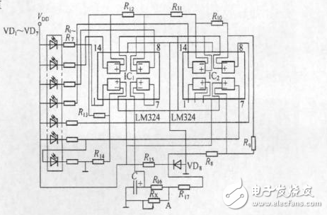
Figure 2 Electronic fuel gauge
2) Working principle
When the fuel in the fuel tank is full, the Rx resistance is the smallest, the A point potential is the lowest, the ICI and ICZ voltage comparator outputs are low, the 6 green LEDs are all lit, and the red LED VDI is extinguished, indicating the fuel tank. Full.
When the amount of fuel in the fuel tank is gradually reduced, the resistance value of Rx gradually increases, the potential at point A gradually increases, and the green light-emitting diodes VD7, VD6, VD5, ..., VD2 are sequentially extinguished. The less the amount of fuel, the less the number of green LEDs.
When the fuel in the fuel tank runs out, the resistance is called the maximum, the potential at point A is the highest, the output of the two voltage comparators of ICI and ICZ is high level, the six green light-emitting diodes are all extinguished, and the red light-emitting diode VD1 is bright, indicating the fuel tank. no fuel.
3, speed odometer
The speedometer is used to display the speed and mileage of the car. Commonly used magnetic induction and moving-coil speed odometers, they are composed of two parts: the speedometer and the odometer. The principle is to use the permanent magnet magnetic field and the newly generated magnetic field interaction to drive the pointer to deflect and display the speed. The structure and principle of the speedometer are described below by taking the magnetic induction type as an example.
The structural speedometer consists of a permanent magnet, an aluminum bowl with a shaft and a pointer, a cover, and a dial. The odometer consists of three pairs of worm gears, intermediate gears, and a range counter. The drive shaft of the watch is driven by the transmission output shaft through the gear meshing and the flexible shaft.
1) Working principle
When the car is stationary, the aluminum bowl pointer is at the zero position of the dial under the action of the hairspring. When the car is driving, the drive shaft rotates with a permanent magnet, and the magnetic line magnetizes the aluminum bowl to make the aluminum bowl generate a magnetic field. The permanent magnet magnetic field interacts with the aluminum bowl magnetic field to generate a torque, which overcomes the spring force of the balance spring, and the pointer is rotated by the aluminum bowl. The shaft speed is proportional to the angle, that is, the corresponding vehicle speed is displayed on the dial.
The drive shaft and the worm gear mechanism have a certain transmission ratio. When the car is running, the flexible shaft drives the drive shaft, and after three pairs of worm gears, the first digital wheel on the right side of the odometer is driven and passed from right to left to the rest. The digital wheel accumulates the mileage. At the same time, the gear on the odometer drives the short-range digital wheel through the intermediate gear, and passes it to the left to the remaining digital wheels to record the short-distance mileage. When you need to clear the short mileage record, press the short odometer reset lever to return the indication of the short mileage counter to zero.
4, engine tachometer
The engine tachometer is used to display the engine speed. Commonly used is the electronic tachometer. As shown in Figure 3.
1) Structure
An integration circuit consisting of R1, R2, and C1 (functioning to shape the open/close pulse signal), charge and discharge capacitor C, amplifier tube T, and voltage regulator DZ (to stabilize the charging voltage of capacitor C, improve the measurement accuracy of the tachometer) and Tachometer n and so on. The speed signal is taken from the pulse signal of the primary circuit of the ignition system. D3 acts as a protection against the transient high voltage breakdown of the T collector.
2) Working principle
When the engine works to close the breaker contact K, the base strap of the triode T is unbiased in the off state, and the positive pole of the power supply → R3 → C → D2 → grounding → the negative pole of the power supply. Capacitor C is charged; when the contact is open, the base potential of the triode T is close to the power supply voltage, and T is turned from off to on. At this time, the charge on the capacitor C is full → T → tachometer n → diode D1 → C The discharge circuit drives the tachometer. The contacts are repeatedly opened and closed, and the capacitor C is continuously charged and discharged, so that the tachometer n displays the average value of the passing current. The opening and closing frequency of the breaker contact is proportional to the engine speed, and the average value of the discharge current through the tachometer n is also proportional to the engine speed.
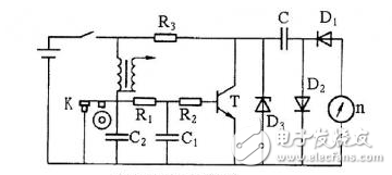
Figure 3 Electronic tachometer
· Backup Camera Blind Spot Camera When Parking Backing Reversing Your Trailer to Get Decent Image Quality to Make Your Reversing More Confident and Safety.
· Rear View Backup Camera and Monitor Kit : Waterproof Camera With Infrared Lights and HD Sensor & Night Vision.
· Reverse Backup Car Dash Security Sensor Camera For Trucks RV , Will Offer Much Safety Drive With It ,Extra Eyes on Trucks Behind and Side.
·
Quad Backup Camera Monitor System
Backup Camera Monitor,Quad Backup Camera Monitor System,Quad Split Monitor,Wired Quad View Monitor
Shenzhen Sunveytech Co.,LTD , https://www.sunveytech.com