THD (total harmonic distorTIon): An indicator of signal harmonic distortion expressed as the ratio of the sum of the power of all harmonic components to the fundamental frequency signal power. Lower total harmonic distortion causes devices such as audio, electronic amplifiers, or microphones to produce more accurate, less harmonic, output signals that are close to the original sampled signal.
For a higher audio system fidelity, the article will introduce a new concept. Many systems, especially those used in the home theater/mini-small band market, are cautiously adding distortion to the output signal. Although this does not seem to be in line with our common sense, there are reasons for designers to consider doing so. The main purpose of this technique is to maximize the average power output while limiting the appearance of peaks.
Some customers use the same power amplifier IC in a number of products. This allows them to purchase a device in larger batches, reducing costs and simplifying inventory. They may use a small power source to save costs. The customer will use a closed loop, fixed gain amplifier with a small power supply. It limits the output voltage swing (by limiting the output), which protects the low-power supply from overcurrent conditions. However, a simple attenuator can make the system quieter. A little distortion of the output can greatly increase the perceived RMS power. Be cautious when determining the degree of distortion, and don't add too much!
For other customers, limiting the voltage output of their signals can help limit speaker drift. However, care should be taken in this case because the high RMS power entering the speaker can cause reliability problems.
In digital processing systems, THD can be introduced by saturating digital samples to the signal. That is, using enough gain, the most significant bit is shifted out of the digital sample size. For example, if you have a 24-bit word, your sample is 0x900000. With 12 Db gain, the highest audio bit exceeds the most significant bit (MSB) of the sample.
After that, downgrade the data to the audio output level you need. So, it can be summarized as:
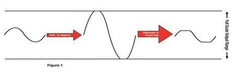
Figure 1 Amplifies the signal to increase THD for clipping, then lowers the output to produce a more average power from a specific peak to peak voltage.
This sounds simple, but many audio processors are not actually the most significant bits = full-scale audio. For example, some TI audio processors use a data format called 9.23. This sampled data can be used to represent 16-bit or 24-bit data in the following ways:
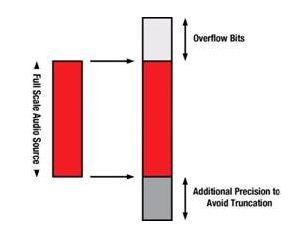
Figure 2 Mapping standard 16-bit or 24-bit audio samples to 32-bit or 48-bit memory locations
As you can see, the MSB and LSB add some padding. LSB is easy to understand - if you cut a 16-bit word (using a CD player), you still have some bits that you can copy without cutting.
At the top, there are 9 bits to prevent accidental saturation of audio data. For example, if you use a 24-dB boost equalizer (EQ) and you enter a “full scale†16-bit word, you may unintentionally saturate the signal, which increases distortion, and this is with us. The direction of hard work runs counter to each other.
There is amplitude loss when clipping, so THD (post) may allow a small amount of gain to pass through the THD manager. 10% distortion clipping results in approximately -1dB output level loss.
In our case, the system has a 9.23 audio path. We want to generate 10% THD at –12 dB output. The average input is –10 dBFS (–10 dB reference 24-bit full-scale audio source).
We need to zoom in to full scale and above ("overflow" 9 digits). Therefore, in a boost module, we add 10 dB to the original source to reach full scale, then add 27 dB to fill the 9 overflow bits. Now, increase the gain by 3dB to clip the signal. In total, we need to increase the gain by 40dB.
Now we have a signal that fills the audio path MSB and requires a cut so that the output can be output at –12 dB. This means a 39dB reduction. The resulting output has 10% distortion and an output level of –12 dB. Look! We have now increased RMS power (by adding distortion) at –12 dB output while making the power supply and speakers work even easier.
Connector technical data collection - invisible giants, insight into connector status and trends
Applications:
The use of a K-rated transformer is anywhere non-linear loads are present. Prime uses would be in factory automation, computer rooms, and office buildings because of the high harmonic content in these areas, Typically a K-13 rated transformer is sufficient for most applications. UL recognizes K-factor values of 4, 9, 13, 20, 30, 40 and 50. The K-factor number tells us how much a transformer must be de-rated to handle a definite non-linear load or, conversely, how much it must be oversized to handle the same load.
How to choose your K factor transformer?
K1: standard transformers, standard lighting, motors.
K4: Induction heater, SCR, AC drive
K13: School pulse lighting, hospital
K20: Data processing computer, computer room.
Or send your requirement to SCOTECH!
Why SCOTECH
Long history- Focus on transformer manufacturing since 1934.
Technical support – 134 engineers stand by for you 24/7.
Manufacturing-advanced production and testing equipment, strict QA system.
Perfect service-The complete customer service package (from quotation to energization).
K Rated Transformer,K4 Rated Transformer,K13 Rated Transformer,K Factor Power Transformer
Jiangshan Scotech Electrical Co.,Ltd , https://www.scotech.com