Beginning in the 1980s, the application direction of RF microwave circuit technology gradually shifted from traditional waveguide coaxial devices to microwave planar PCB circuits. Microwave planar circuit design has always been a complicated task. Today's wireless communication products have gradually evolved from the early 2G to 3G, 4G and even 5G.
With the gradual increase of the application frequency, coupled with the coexistence of multi-band circuits and product miniaturization requirements, the design of RF circuits is becoming more and more difficult, and the traditional design methods can no longer meet the design requirements of modern RF communication products. Therefore, it is imperative to use the RF microwave simulation software for circuit design.
What is RF simulation software?
The RF simulation software is a computerized product of computational electromagnetics and mathematical analysis research results. It integrates electromagnetics, mathematical analysis, virtual experiments and other methods into one, and achieves the expected experimental results through simulation methods, and obtains various intuitive data. It is a powerful tool for RF engineers and researchers. The RF simulation method is a scientific design method, which can reduce the debugging workload and various unfavorable factors that may occur in the later stage of the product, thereby shortening the product development cycle and improving the one-time success rate of the product.
The RF circuit design simulation software is currently the mainstream Keysight ADS (Advanced Design System). The ADS software provides comprehensive standards-based design and verification by means of the wireless library in the integrated platform and the circuit system and electromagnetic co-simulation function. It has been widely used in Wifi, GPS, Bluetooth, 2G/3G/4G circuits and communication system design.
Let's take ADS software as an example to explain the basic process of circuit design.
RF circuit design and simulation involves the following steps:
1. System simulation phase:
In the initial stage of product certification, first determine the system's system indicators and determine the circuit architecture, including: sensitivity, total front-end gain, noise figure, operating bandwidth, dynamic range, etc. These need to use ADS to simulate the circuit. Because most of our products are now derived from mature foreign solutions, the chip and circuit system architecture are determined, so this step is currently not involved in consumer products.
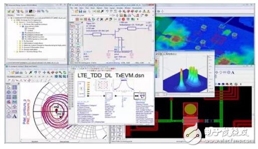
ADS multi-layer simulation
2. Schematic design simulation stage:
The scheme and IC selection are performed according to system specifications, including low noise amplifier LNA, filter, power amplifier design, and interstage matching circuit.
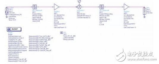
RX receive link system simulation
3. PCB joint simulation stage:
Schematic design is actually an ideal situation, it does not consider the parasitic effects of the device and the coupling effect of the PCB microstrip line. Therefore, the scientific approach is to introduce the designed PCB into the ADS Momentum for electromagnetic field simulation and re-adjust the matching component values. According to RF Sister's many years of experience, if the model and simulation settings are normal enough, the simulation results are very close.
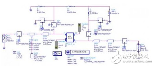
Low noise amplifier schematic simulation
4. Product commissioning phase:
In fact, the simulation can only guarantee the correctness of the design trend and direction. Therefore, after the template comes back, it still needs to be debugged and optimized, and the test results are recorded and saved, and compared with the simulation. In principle: no matter how big the difference, be sure to find the reason!
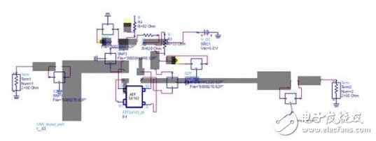
Combined simulation of PCB low noise amplifier
5. Project summary stage:
Closed-loop analysis of the entire simulation and actual test results - whether it is a model problem, or a problem of setting the simulation parameters, or a problem of inaccurate PCB dielectric constant and dielectric loss, is it a processing problem? Here, we need a lot of practical experience and problem analysis skills. The final summary is very important and will be the basis for the next step of success. Similar to large enterprises such as Huawei ZTE, there will be a habit of writing summary documents.

Comparison of an LTE terminal simulation and measured input impedance
Tips
The method is always good, but the process is always tortuous. Many of the small partners fell for the first time (the difference between the actual measurement and the simulation), and they gave up. The simulation and testing are close. In fact, it depends on the following factors:
(1) Proficiency in the use of simulation software. Need to understand the basic principles of simulation, know the specific meaning of each item's settings, whether it will affect the parameters;
(2) Whether the test method and network calibration are correct enough. Understand what SOLT, TRL, and what are their advantages and disadvantages;
(3) The understanding of component characteristics, S-parameter model and SPICE model is not deep enough;
(4) Whether the experience is sufficient. No experience with closed-loop verification, think that it can be closed once;
(5) The most important point: the small partners have research interests, but because the company's product progress, so did not do too much in-depth thinking and more analysis time.
KNM5 series Moulded Case Circuit Breaker is MCCB , How to select good Molded Case Circuit Breaker suppliers? Korlen electric is your first choice. All moulded Case Circuit Breakers pass the CE.CB.SEMKO.SIRIM etc. Certificates.
Moulded Case Circuit Breaker /MCCB can be used to distribute electric power and protect power equipment against overload and short-current, and can change the circuit and start motor infrequently. The application of Moulded Case Circuit Breaker /MCCB is industrial.
Korlen electric also provide Miniature Circuit Breaker / MCB . Residual Current Circuit Breaker /RCCB. RCBO . Led light and so on .
KNM5 Series Moulded Case Circuit Breaker
KNM5 series Molded Case Circuit Breaker,Small Size Molded Case Circuit Breaker,Electrical Molded Case Circuit Breaker,Automatic Molded Case Circuit Breaker
Wenzhou Korlen Electric Appliances Co., Ltd. , https://www.korlenelectric.com