The Cadence Allegro System Interconnect Platform is designed to streamline the creation of high-performance interconnects across ICs, packages, and PCBs. By leveraging application platform collaborative design methods, engineers can rapidly optimize system-level interconnects between I/O buffers and across different components. This approach significantly reduces the need for hardware rework, lowers costs, and shortens the overall design cycle. The constraint-driven Allegro process includes advanced tools for design capture, signal integrity analysis, and physical implementation. Combined with support from the Cadence Encounter and Virtuoso platforms, Allegro enables seamless collaboration throughout the design chain.
**Allegro quickly sets the grid point method**
**Step 1:**
Create a new document: xxxxx.txt
Write the following code:
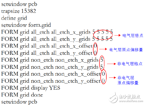
```
Setwindow pcb
Trapsize 15382
Define grid
Setwindow form.grid
FORM grid all_etch all_etch_x_grids 5 5 5 5 5
FORM grid all_etch all_etch_y_grids 5 5 5 5 5
FORM grid all_etch all_etch_x_offset 0
FORM grid all_etch all_etch_y_offset 0
FORM grid non_etch non_etch_x_grids 5
FORM grid non_etch non_etch_y_grids 5
FORM grid non_etch non_etch_x_offset 0
FORM grid non_etch non_etch_y_offset 0
FORM grid display YES
FORM grid done
Setwindow pcb
```
**Step 2:**
Save the txt file as a logical file: xxxxx.lgc
**Step 3:**
Add the following command in the env file:
```
Alias ~2 replay xxxxx.lgc
```
**Step 4:**
Place the xxxxx.lgc file in the same directory as your .brd file.
**Step 5:**
Press Ctrl+2 to switch the grid layout.
**Note:**
You can customize the grid points and shortcut keys based on your personal preferences. This method offers a fast and efficient way to adjust the grid settings in Allegro, improving workflow and productivity during PCB design. Whether you're working on a simple board or a complex multi-layered design, this technique can save time and enhance precision.
AS-i Passive Distributor
The AS-I (i.e. actuator-sensor interface) bus belongs to the bus system at the bottom device level. It is a two-wire network for digital input and output, which complies with EN50295 and IEC62026-2 specifications.
Various types of digital devices can be connected, such as: Sensors, limit switches, buttons, valves, relays, light curtains and emergency stop switches, etc., and send signals to higher-level controls such as PC, PLC, CNC or DCS system. In general, AS-I does not require shielded cables and terminal resistors.
The unshielded two-wire cable used carries both the signal and the power. Generally speaking, the AS-I bus system is simple and reliable, easy to install and fast to configure, and is widely used in industrial automation fields such as logistics, automobile production, petrochemical industry, and elevator control.
The As-I Passive Distributor simple module is pierced and connected to the flat cable, which is suitable for installation in a narrow space, and can provide connection methods such as aviation connectors.
As-I Passive Distributor,As Interface Distributor,Distributor With Pur Cable,Custom As-I Passive Distributor
Kunshan SVL Electric Co.,Ltd , https://www.svlelectric.com