Arduino is an open-source hardware platform developed in Italy, widely used for building interactive electronic projects. Among its many models, the Arduino Uno is the most popular and beginner-friendly board. With various peripheral components like sensors, switches, and LED displays, even those with basic knowledge of electronics can quickly create functional and interesting circuits using this platform. In this article, we will first introduce the key components of the Arduino Uno development board.
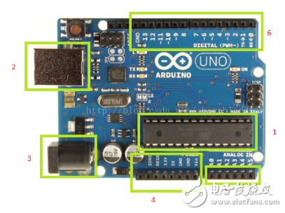
**Figure 1: Arduino Uno Development Board**
1. **Microprocessor:** The heart of the board is the ATmega328, an 8-bit microcontroller with 32KB of flash memory (0.5KB reserved for the bootloader), 2KB of SRAM, and 1KB of EEPROM. It runs at a clock speed of 16MHz, making it powerful enough for most simple to medium-level projects.
2. **USB Interface:** This port allows you to connect the board to your computer for both programming and power supply. It acts as a bridge between the Arduino and your development environment.
3. **External Power Supply:** When the board is not connected to a computer, an external power source such as a 9V battery can be used to power the device, enabling standalone operation.
4. **Power Pins & Ground:** The board provides 5V and 3.3V outputs, and the Vin pin can be used to power the entire circuit directly from an external power source.
5. **Analog Inputs:** There are six analog input pins that support 10-bit resolution, allowing you to read values ranging from 0 to 1023.
6. **Digital I/O Pins:** The Uno has 14 digital input/output pins. These can be configured as either input or output through your code. Pins 0 and 1 are used for serial communication, while pins 3, 5, 6, 9, 10, and 11 support PWM (Pulse Width Modulation) output. Pin 13 is connected to an onboard LED, which turns on when the pin is set to HIGH.
Now that we've covered the hardware, let's take a look at the Arduino development environment. You can choose different versions based on your needs. Once installed and launched, the interface is user-friendly and intuitive, as shown in Figure 2.
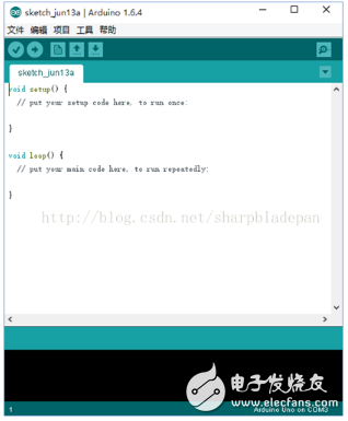
**Figure 2: Arduino Development Tool Interface**
When connecting the board to your computer via USB, it’s important to install the correct drivers. These are usually found in the "drivers" folder within the Arduino software directory, such as `f:\arduino-1.6.4\drivers\`. After installation, you should see the corresponding COM port, as shown in Figure 3.
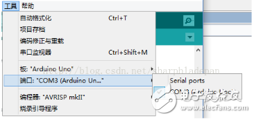
**Figure 3: Port Detection After Driver Installation**
In the Arduino IDE, there are two main functions: `setup()` and `loop()`. The `setup()` function runs once when the program starts, typically used for initializing pins or setting up variables. The `loop()` function runs repeatedly, making it the core of your program logic. You can place all your main operations inside this loop to control how your project behaves over time.
Rf Coaxial Connector,Female Smb Coaxial Connector,Mcx Coaxial Cable Connector,Mcx Coaxial Connector
Changzhou Kingsun New Energy Technology Co., Ltd. , https://www.aioconn.com