The TL431 plays a crucial role in the feedback loop of switching power supplies (SMPS). It functions as a reference voltage combined with an open-collector error amplifier, making it cost-effective and easy to use. Despite its long-standing popularity, some designers overlook its bias current, which can negatively impact system performance.
A simplified schematic of the TL431 is shown in Figure 1. The circuit includes a reference voltage and an error amplifier that drives an NPN transistor. In this closed-loop system, a portion of the output voltage is compared to the internal reference voltage (Vref) of the TL431.
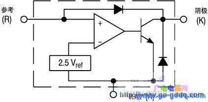
**Figure 1: TL431 Equivalent Circuit**
Another simplified DC model of the SMPS is presented in Figure 2. Here, Vout is compared to Vref via a resistor divider, and the theoretical output voltage is Vref divided by α. However, the actual output voltage is influenced by various gains and impedances in the system. This relationship is expressed in the following equations:
$$
V_{out} = \frac{V_{ref} \cdot \beta \cdot G}{1 + \alpha \cdot \beta \cdot G + \frac{R_{SOL}}{R_L}} \quad (2)
$$
$$
\text{Static Error} = \frac{V_{ref}}{\alpha} - V_{out} = \frac{V_{ref} \cdot (R_{SOL} + R_L)}{\alpha \cdot (R_{SOL} + \alpha \cdot \beta \cdot G \cdot R_L + R_L)} \quad (3)
$$
From equation (3), it's clear that increasing the gain helps reduce static error and improve output voltage accuracy. Another important factor affected by the gain loop is the system’s output impedance. By simplifying the system to its Thevenin equivalent, we can calculate the output impedance (Rth) using the no-load voltage (Vth) and the load resistance (RL).
When the load resistance equals the closed-loop output impedance (Rth), the output voltage drops to half of Vth. This allows us to compute Rth, also known as RSCL, using the following equation:
$$
RSCL = \frac{R_{SOL}}{1 + \alpha \cdot \beta \cdot G} \quad (5)
$$
This equation shows that a higher DC gain reduces the closed-loop output impedance, improving stability and dynamic response. To maintain high DC gain, most SMPS designs use a pure integrator configuration for the TL431, as shown in Figure 3.
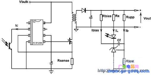
**Figure 3: TL431 in Conventional Shunt Regulator Configuration**
In the absence of Rbias, the bridge current must be greater than the TL431’s reference pin bias current (up to 6.5 mA). For a 12V output, assuming a bridge current of 1 mA, Rlow and Rupp can be calculated accordingly. However, reducing the bridge current may help lower standby power consumption under no-load conditions.
The resistor RS must supply enough current to activate the optocoupler’s collector pin. If the optocoupler has a low current transfer ratio (CTR), RS should be chosen carefully to ensure proper feedback. For example, with a CTR of 150%, the required current through the LED is reduced, affecting the feedback loop.
To address these issues, adding a bias resistor (Rbias) ensures a stable bias current for the TL431. Calculating Rbias based on worst-case scenarios—such as heavy load and high CTR—ensures consistent performance. Experimental results show that adding a 3.3kΩ bias resistor significantly reduces the output impedance from 57mΩ to 4mΩ, as illustrated in Figure 4.
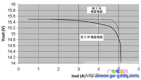
**Figure 4: Impact of Bias Current on TL431 Performance**
In conclusion, properly biasing the TL431 with an external resistor is essential for optimal performance. If minimizing no-load power is a priority, alternatives like the TLV431 or NCP100 offer lower bias currents and smaller reference voltages. Additionally, choosing a resistor value close to standard values (e.g., 1kΩ) can simplify design and improve reliability.
On And Off Grid Inverter
A luminous Solar Inverter is a type of device used in solar power systems that offers additional features beyond those provided by a standard string inverter. The on Off Grid Inverter combines the functions of a traditional solar inverter with a battery charger and can also act as a backup power source during grid outages.
Features
1. Battery Charging: Hybrid inverters have built-in charge controllers that allow them to efficiently charge batteries from the solar panels. This feature enables homeowners to store excess solar energy for use when the sun isn't shining, providing a more reliable and independent power supply.
2. Grid Tying and Islanding: These inverters can operate in both grid-tied mode (feeding excess power back into the grid) and off-grid or islanding mode (powering the home directly from the stored solar energy without connecting to the grid). This versatility allows the system to adapt to different power needs and grid conditions.
3. Energy Management: Hybrid inverters often come equipped with advanced software that allows for sophisticated energy management. This includes the ability to prioritize the use of solar energy, manage battery discharge, and optimize energy usage within the home.
4. Communication Capabilities: Many modern hybrid inverters include Wi-Fi or Bluetooth connectivity, enabling remote monitoring and control of the solar system through smartphone apps or web interfaces.
5. Backup Power: In the event of a power outage, a hybrid inverter can switch over to battery power, ensuring that critical loads continue to be powered even when the grid is down.
6. Efficiency: Hybrid inverters are designed to maximize the efficiency of solar power generation and storage, making them an attractive choice for homeowners looking to reduce their reliance on the grid and lower their electricity bills.
Overall, a hybrid solar inverter provides a comprehensive solution for harnessing and managing solar energy, offering benefits such as increased energy independence, cost savings, and enhanced reliability in power supply.
Luminous Solar Inverter,On Off Grid Inverter,On Grid Off Grid Hybrid Energy Storage Inverter,On Off Grid Hybrid Solar Inverter
Ningbo Taiye Technology Co., Ltd. , https://www.tysolarpower.com