Abstract: The combination of wireless module and vehicle driving recorder can be used to obtain the information of vehicle driving recorder in real time and accurately with PC. The system design of the car tachograph with wireless module is elaborated. The system integrates data storage, data acquisition and data analysis. It focuses on the hardware structure design and software design of the car tachograph and the actual application. The wireless collision problem presents a solution.
Key words: LPC2214; SRWF-1021; car recorder; anti-collision
0 Introduction With the rapid development of China's national economy, the heavy and extraordinarily large road traffic accidents of muck trucks and long-distance passenger vehicles have caused huge losses to the country and people's lives and property. In order to carry out in-depth prevention and reduction of road traffic accidents nationwide, many enterprises and scientific research units in China have developed automobile driving recorders. However, the existing recorders use wired methods to read, which is very inconvenient for the law enforcement traffic police. The traffic police rarely operate; it is convenient and fast to read the data wirelessly, and will be welcomed by the law enforcement traffic police. Therefore, the development of wireless reading It is imperative to take data from a car recorder.
The vehicle driving recorder (commonly known as the car black box) is a digital electronic recording device that records, stores, and outputs data of the vehicle's traveling speed, time, mileage, and other state information about the vehicle's travel. It plays an important role in curbing the traffic violations such as fatigue driving, vehicle overspeed, restricting the driver's bad driving behavior, ensuring the driving safety of vehicles and road traffic accidents. In recent years, some provinces in China have already stipulated that long-distance passenger vehicles must be equipped with a vehicle driving recorder.
In this paper, according to the national standard GB/T 19056-2003 of the vehicle driving recorder, a function of complying with national standards and adding anti-collision wireless data uploading to the existing automobile tachograph products is designed. The following mainly describes the basic functions of the car tachograph and the design of the hardware architecture and software system.
1 Basic functions of the vehicle tachograph The national standard GB/T 19056-2003 mainly requires the recorder to have the following functions:
(1) Self-test function When the recorder starts working, it should first perform self-test. After the self-test is normal, it should be instructed to work normally with green flash signal and display mode.
(2) Data collection, recording and storage functions Real-time measurement, recording and storage of time, date, driving time, vehicle speed, mileage and other data, and ensure that stored data is not lost for a long time. The input signals that need to be acquired include three types: analog signal input, digital signal input, and digital signal input.
(3) Overspeed, driver fatigue driving alarm, record When the vehicle speed exceeds the limit (can be set according to user needs), the recorder will give an audible and visual alarm to remind the driver to slow down. The alarm interval is 4s.
When the same driver drives for more than 4 hours, the recorder will record the driver's fatigue driving data and send a buzzer alarm, while the red light flashes, similar to the overspeed alarm. After continuous driving for more than 20 minutes, the recorder automatically cancels the accumulation of the current fatigue time. If the parking time is less than 20 minutes, the recorder is still regarded as continuous driving, accumulating fatigue driving time.
(4) Driver identity record function Each recorder is equipped with a unique serial number, and a non-contact RF IC card checker is installed, or a key password mode. The user can use the IC card method or type password to verify driving. The identity of the staff. If the user is not authenticated before driving, or the authentication is invalid, the default is the last driver's identity. The recorder management software can be used to conveniently view driver identification data. If the driver's identity verification is invalid, it does not affect driving, but the relevant data of illegal driving can be viewed through the management software.
(5) Data display The speed detection is synchronized with the vehicle speed meter. The digital display has a detection accuracy of ±50 r/min and a display range of 0 to 9 999 r/m. The engine speed characteristic factor can be set by the recorder management software.
Date and time recording format: Beijing time * year * month * day * hour * minute * seconds, relative error: ± 5 s.
(6) Data communication function The recorder can communicate with the external environment through various methods (including RS 232 serial interface, USB interface and I2C bus interface) to realize data interaction.
Most of the existing car tachograph data uploads are wired transmissions, such as USB, serial cable transmission, and the like. In the case where wired transmission cannot be used, it is a reasonable solution to use a combination of a wireless data transmission module and a single chip microcomputer for data transmission. This article is to use LPC2214 and SR-WF-1021 digital transmission module combined with a simple anti-collision algorithm for data communication.
2 system hardware design This paper designed a simplified embedded wireless data acquisition system based on LPC2214 microcontroller, the system block diagram shown in Figure 1. The system is small in size, light in weight, low in operating cost, and relies on the existing wireless module self-organizing network to customize the communication protocol. It is especially suitable for occasions where the collection point is widely distributed, the quantity is large, and the automation is on duty.
This article refers to the address: http://
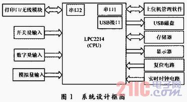
The host part of the system includes: signal input, data storage and processing, data display, data communication, reset circuit and power-down protection circuit.
Real-time clock circuit, LPC2214 can read and save real-time time directly from the real-time clock circuit for violations such as overspeed and fatigue driving.
The system has a USB interface. When the user inserts a USB disk, the host USB function can be used to import the data in the memory to the disk. The PC software can use the data collected by this USB disk for data analysis and vehicle and personnel management.
The reset circuit can not only reset the system, but also can handle some of the interference signals in the wireless communication to cause the wireless module to block the communication, and the power monitoring chip in the LPC2214 can improve the reliability of the system, thereby ensuring the LPC2214 to the power supply, the clock source and the like. The higher requirements are raised.
2.1 CPU Module The CPU module in the system is a high-speed processor LPC2214 based on a 32-bit ARM7TDMISTM CPU that supports real-time simulation and tracking. The LPC2214 features 256 KB of embedded high-speed FLASH memory. The 128-bit wide memory interface and unique acceleration structure allow 32-bit code to run at maximum clock rates. Applications that have tight control over code size can use 16-bit Thumb mode to reduce code size by more than 30% with minimal performance loss. The LPC2214 is available in a 144-pin package and can be used with up to 76 GPIOs (using external memory) to 112 (single-chip applications). Thanks to the built-in wide range of serial communication interfaces, they are ideal for communication gateways, protocol converters, embedded soft modems, and many other types of applications.
2.2 Data Acquisition The analog acquisition in this paper directly uses the existing successive approximation 10 b A/D converter in LPC2214 to realize the acquisition of 8 fast analog signals. The converter's measurement range is 0 ~ 3 V, the fastest conversion speed can reach 2.44μs / time, programming is simple, you can also select the required function to improve the conversion accuracy of the converter.
In this paper, the 8-channel switch is used for the digital acquisition. The external switch signal is introduced into the system from the 8 I/O ports of the LPC2214 after the optical isolation TLP421. The 8-channel switch signal is programmed by interrupt mode or query mode. collection.
2.3 Data Storage Module The system uses LPC2214 as the core to collect three kinds of signals: external analog input, digital input and digital input. The data to be saved is processed and stored in the internal mass storage. Real-time data (such as real-time vehicle speed, driver information, real-time time) and alarm signals can be displayed on the display panel.
This system contains two kinds of memory: FLASH memory SST39VF160 and E2PROM memory FM24CL64. The schematic is shown in Figure 2.
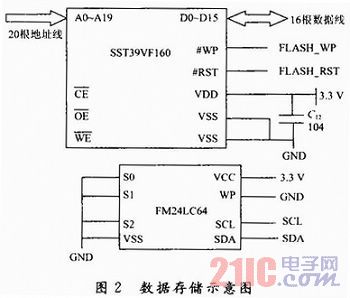
SST39VF160 is a 1M×16 CMOS parallel multi-function FLASH memory with fast erase sector and software and hardware write protection. Because the chip power-down data retention time is more than 100 years, it is very suitable for large-capacity data storage, especially the need for program or data memory to be easily and cost-effectively updated.
The FM24CL64 is an I2C bus-based serial CMOS E2PROM memory with 8 KB of memory and has a dedicated write protection feature. The chip occupies less LPC2214 I/O resources, simple programming, data storage time can reach 100 years, so it is often used to store some systems, configuration parameters, and is widely used in instrumentation.
2.4 External SDRAM Module In this system, a high-speed static RAMIS61LV25616 is extended. This device is manufactured by ISSI's high-performance CMOS technology and features low power consumption and fast access speed. The large-capacity SDRAM resources provide a solid foundation for the transplantation of embedded operating systems and complex logic processing.
2.5 Communication Module The LPC2214 integrates two 16C550 industry standard UART serial interfaces, and uses the UART1 external expansion SP3232 chip to form a standard RS 232 communication interface. The collected data can be transmitted to the PC through the RS 232 bus, which is convenient for data storage and processing.
The UART0 external expansion SRWF-1021 wireless data transmission module provides a convenient transparent wireless transmission method for data communication between the recorder and the PC. This module is mainly used for industrial control. Its outstanding features are: realize transparent wireless transmission of serial port, real-time stable and reliable high speed, and simple configuration. The collected data is transmitted wirelessly, and the application is flexible, and can work well in an environment that is not easy to be wired.
The SRWF-1021 wireless data transmission module is a universal transparent transmission module that can adapt to any standard or non-standard user protocol. Its features are as follows:
(1) Micropower transmission with a maximum transmit power of 17 dBm and a carrier frequency of 433 MHz.
(2) High anti-interference ability and low error rate, based on GFSK/FSK modulation method, using efficient forward error correction channel coding technology to improve the ability of data to resist burst interference and random interference.
(3) The transmission distance is long. In the case of highway, the antenna is placed at a height of 2 m and the transmission distance is up to 800 m (433 MHz@9 600 b/s).
(4) Provide a transparent data interface, which can adapt to any standard or non-standard user protocol, and automatically filter out the fake data generated in the air. The user does not need to prepare redundant programs to realize the receipt and delivery.
(5) The standard configuration provides 8 channels and can be extended to 16/32 channels. Meet the user's multiple communication combinations.
(6) Provide two serial port interfaces, COM1 is TTL level.
(7) UART interface, COM2 is user-defined as software simulation RS 232/RS 485 interface, the user only needs to plug and unplug the 1 bit short circuiter and then power on to define.
(8) The baud rate of the interface is variously selectable, and the format is also user-defined. It can transmit infinitely long data frames, and the user programming is flexible.
(9) With +5 V supply, the receiving current is (28 ± 2) mA, the emission current is (90 ± 5) mA, and the sleep current is (5 ± 2) μA.
(10) It adopts single-chip radio frequency integrated circuit and single-chip MCU, which has small volume, few peripheral circuits, high reliability and low failure rate.
3 system software part The software design of wireless communication system includes three parts: single chip end, PC end and upper computer management analysis software. The three parts of the software work together to achieve half-duplex communication.
The MCU software requires the car black box as an instrument to record the running state of the car. In an uncontrolled environment, it automatically runs as the car starts running.
The operation mode of the car black box is as follows: After the system is powered on, the system boot program is started, and the embedded Linux kernel is called by the boot program. After the operating system runs, the operating system automatically starts the main program of the system. The system software adopts the structure of the interrupt service program and the centralized control of the CPU. The main control program is responsible for system initialization, manipulating and interacting with the hardware devices of each module; and each module sends a request to the main control program in an interrupt manner, requiring the main control program to complete the corresponding operation.
The upper computer management analysis software is provided to the vehicle management center personnel. On the one hand, it can collect all vehicle information and driver information under the management center for unified numbering and management; on the other hand, it can collect real-time data of vehicle travel. Master the driver's driving situation. In addition, it can also conduct accident analysis and identification of vehicles with accidents, and provide corresponding traffic accident identification reports for the traffic department and law enforcement departments.
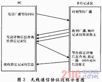
The communication between the recorder and the PC can be single point to single point, single point to multi point, multi point to multi point communication. Sending broadcast information is single-to-multipoint communication or multi-point to multipoint communication. However, detailed information such as fatigue, timeout, and overspeed is single-point to single-point communication. The wireless communication protocol implementation process is shown in Figure 3.
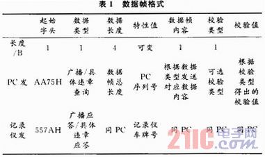
3.1 Design of wireless communication protocol In wireless communication, due to the interference of the external environment, the error rate is usually high. Therefore, the design of the communication protocol is very important to ensure the reliability of communication. The design of the protocol is mainly the design of the frame structure. In the wireless communication system, there are instruction frames and data frames. The contents of the data frame include the start byte, the data length byte, the data byte, the end byte, and the checksum. The communication communication convention specified in the National Standard for Vehicle Recorder is as follows:
(1) The data exchange between the communication machine (computer or data acquisition instrument) and the recorder is transmitted by frame. The communication mode is asynchronous serial mode, which contains a start bit, 8 data bits, a stop bit, odd parity. . The data in this protocol uses hexadecimal encoding, 8421BCD code and ASCII character code.
(2) Using RS 232 interface, the data transmission rate is 9 600 b/s.
(3) The scope of the check shall include all bytes before the check byte, and the value is the XOR result between these bytes.
(4) The data block is the parameter or data associated with the command word attached to the data frame. When it is 0, there is no data block or parameter in the frame. This situation occurs in the data upload "command frame" and data downlink. In the response frame".
(5) The length of the data block refers to the length of the parameter or data associated with the command word attached to the data frame. It is expressed in bytes. The effective length is 0 to 64 KB. When it is 0, there is no data block in this frame. Or parameter, this happens in the data upload "command frame" and the data is sent in the "answer frame".
According to the data format requirements in the national standard, the data frame format of the system design is shown in Table 1.
3.2 Simple anti-collision algorithm design Because of the openness of wireless data transmission, and after the PC sends the broadcast information, the response data response of all the recorders receiving the broadcast is basically simultaneous, which will inevitably generate wireless data. The problem of collision.
To prevent collisions when different recorders upload data wirelessly. In this paper, various existing anti-collision algorithms have been tried in the design. However, given the scope of application of this system, the existing algorithms are too complicated.
According to the scope of application, the system will be mainly applied to places where vehicles such as toll gates stay for a short time, with short time and small range. Then, where the response of the recorder code is sent, a valid delay is sent: the result obtained by multiplying the number of the license plate number by the number of random numbers within 1 to 10, in milliseconds. In this way, the response messages of each vehicle can be effectively responded to the PC in an orderly manner.
The experimental results after adding this delay improvement code show that the correct rate is as high as 99%, and the correct rate of this simple anti-collision algorithm is only 90%.
4 Conclusions This article only adds the PC's real-time access to the wireless transmission of the recorder's travel data based on the original simple car recorder, and adds a simple anti-collision algorithm to reduce the collision of wireless data transmission. It can avoid some problems that require the use of GPRS and other traffic charges, and reduce the use cost. I believe that with the development of national technology, the system can get more understanding and application.
Polycrystalline Solar Panels is composed of polycrystalline silicon solar cells, EVA film low toughened glass, light electroplating rate gold. Polycrystalline silicon is an aggregate containing a large number of single crystal particles. Typically, Polycrystalline solar panels have an efficiency of about 18 percent. Output power of polycrystalline solar panels is strictly controlled at + / - 3% to ensure positive tolerances for each container. Its components are tested by internationally renowned laboratories to ensure the accuracy of output common rate. In the process of component production, advanced technology without screw built-in corner key connection is applied to tighten seal, with high mechanical strength and high transmittance, toughened glass package and sealed waterproof junction box are adopted to ensure the safety of components. The output power of these pv modules is guaranteed to be over 90% during the 10 years of use. During 25 years of use, the output power is above 80%. The packaging form and accessories such as junction boxes selected by polycrystalline solar panels meet the requirements of field use and the protection level reaches IP65. The module can resist wind speed of 120Km/h, and its strength can resist general wind sand, hail and snow pressure.
Polycrystalline Solar Panels
Polycrystalline Solar Panels,Polycrystalline Solar PV Panels,Polycrystalline Solar Photovoltaic Panel,Polycrystalline Photovoltaic Solar Panels
ZHEJIANG FIZZ NEW ENERGY CO.,LTD , https://www.ywfizz.com