1 Introduction
As a new light source in the 21st century, semiconductor lighting has the advantages of energy saving, environmental protection, long life and easy maintenance. It is an irresistible trend to replace traditional lighting sources such as incandescent lamps and fluorescent lamps with high-power high-brightness light-emitting diodes (LEDs). Due to the characteristics of the LED itself, it must be powered by a constant current source. Therefore, the design of high efficiency constant current driving power supply has become an important research object in LED applications. The LLC half-bridge resonant converter has become a popular topology with its high efficiency and high power density. However, it is generally used in constant voltage output applications. Traditional LLC is considered to be unsuitable for wide-range constant current output. A new design method for the half-bridge LLC is proposed here to maintain high efficiency in a wide range of constant current output applications.
Therefore, LLC can be a good topological choice for LED drivers.
2 Design method of constant current LLC resonant converter
2.1 Half-Bridge LLC Transform Circuit Overview
The circuit principle of the half-bridge LLC resonant converter is shown in Figure 1.
Two switching transistors VS1 and VS2 with a duty ratio of 0.5 complement each other form a half-bridge structure. The resonant inductor Lr, the resonant capacitor Cr and the magnetizing inductance Lm of the transformer form an LLC resonant network, and the transformer secondary consists of a rectifier diode VD1~VD4. Rectifier circuit.
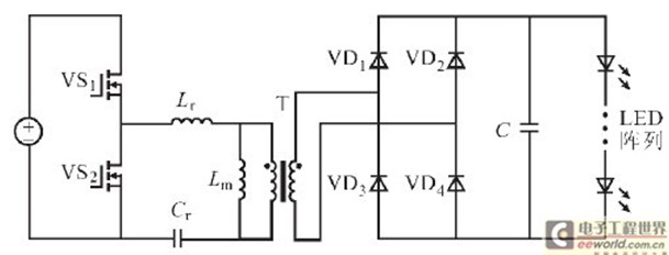
Figure 1 Half-bridge LLC resonant converter circuit topology
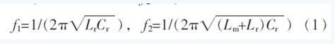
The half-bridge LLC converter has two resonant frequencies. When the primary voltage of the transformer is clamped by the output voltage, Lm does not participate in resonance, and the series resonant frequency generated by Lr and Cr is f1; when the transformer does not transfer energy to the secondary, the Lm voltage is not clamped, and Lm, Lr, Cr participate. Resonance, which constitutes the resonant frequency f2 is:
2.2 DC gain curve and working range
Using the fundamental approximation method, the DC voltage gain expression of the LLC resonant converter can be derived as:
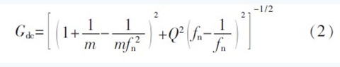
Where: m = Lm / Lr; fn = fs / f1, fs is the switching frequency; Ro is the equivalent output resistance.
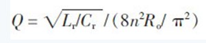
Figure 2 shows the DC gain curve for a half-bridge LLC converter under different load conditions. When LLC operates at f1 (point (1,1) in the figure), the resonant circuit has the lowest impedance and the lowest loss. Therefore, in the ordinary design, the full load working point is generally designed at this point.
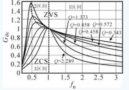
Figure 2 DC gain curve of half-bridge LLC
In the 3 interval shown in Figure 2, the switching transistor operates in the capacitive region and the switching loss is large, so the circuit should be avoided in this area in any design. In the 2 interval, the LLC works in the resonant current discontinuous mode, which can simultaneously turn on the primary switching transistor ZVS and the secondary rectifier ZCS to avoid reverse recovery. Therefore, in the design of constant voltage output, generally under all load conditions. The working point is designed in this interval. However, in the constant current-wide voltage range output design, the load variation is large, and the corresponding DC gain varies widely. It is difficult to ensure that all operating points in the full load range are in the ZVS region. And the circuit works on the curve between the maximum gain point and the (1,1) point. The smaller the gain of this curve, the closer it is to the resonance point. Therefore, only the full load operating point can be designed to have a high DC gain, ie fs
In the interval 1 shown in Figure 2, fs>f1, LLC works in the resonant current continuous mode, the primary switching transistor can realize ZVS turn-on, the secondary rectifier can not achieve ZCS turn-off, there will be reverse recovery process, but the output current In small cases, the impact is small. The slope of this interval gain curve is large, and the range of adjustable DC gain is wide, which can meet the requirements of output design of constant current and wide voltage range.
2.3 Constant current wide voltage range output design
The DC gain of the half-bridge LLC is:
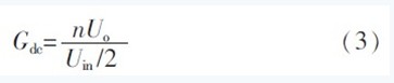
Where: n is the actual transformer winding turns ratio; Uin, Uo are the input and output voltages respectively.
It can be seen that in order to get the best design point (ie resonance point), only the desired transformer winding turns ratio Nnor=Uin /(2Uo) is needed.
As can be seen from Figure 2, the smaller the curve gain, the larger the slope. If the fully loaded operating point is designed at the resonance point, the operating frequency will be reduced to half (ie, Gdc drops to 0.5) and the operating frequency will be more than 2 times the resonant frequency, and the operating frequency range is wide. In order to narrow the operating frequency range, a section with a large slope of the gain curve can be selected, that is, Gdc<1. It can be known from the equations (3) and Nnor that if n
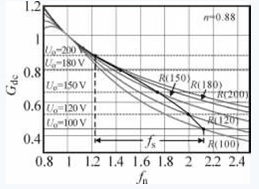
Figure 3 Working point of constant current LLC
In Figure 3, the dotted line is the corresponding Gdc when Uo changes from 200 to 100 V, and the solid line is the gain curve of the equivalent load when Uo is 200~100 V. When Uo is the same, the intersection of the corresponding solid line and the dotted line is the actual circuit. Work point. In this design, when Uo changes from 200 to 100 V, the operating frequency ranges from 1.22f1 to 2.11f1.
3 parameter analysis and optimization
3.1 f1 selection
Considering the design of the magnetic component, the operating frequency of the circuit at full load is ideally designed around 100 kHz. To ensure half-load efficiency, the half-load frequency cannot be too high. Therefore, the section with a large slope in the gain curve should be selected, that is, Gdc<1. The actual operating frequency of the circuit is always greater than f1, so f1<100 kHz should be selected, and the design is reasonable at 60~70 kHz.
3.2 Resonance parameters Cr, Lr
When f1 is constant, the smaller Cr is, the larger Lr is, and the larger Q is, the larger the slope of the gain curve is. Therefore, reducing Cr can significantly reduce the operating frequency of the half load. From the viewpoint of improving the half load efficiency, the smaller the Cr, the better, but the smaller the Cr, the larger the voltage peak at both ends. To reduce the voltage stress of Cr, the larger the Cr should be, the better. The design should be compromised. After Cr is determined, Lr can be calculated according to f1:
3.3 n , Lm selection
In order to narrow the range of the switching frequency, the actual transformer winding turns ratio should be smaller than the desired transformer winding turns ratio, n
From the viewpoint of reducing the conduction loss of the switching tube, the larger the value of the transformer Lm, the smaller the effective value of the primary current, and the smaller the conduction loss of the switching tube, so it is desirable that the larger the Lm is, the better. However, when Lr is constant, the larger the Lm is, the larger m is, and the slope of the gain curve becomes smaller. To ensure that the required Uo widens the operating frequency range of the converter, it will affect the efficiency when Uo is reduced to half. Therefore, under the premise of guaranteeing a certain switching frequency range, the larger the Lm, the better.
The design of all the above parameters needs to comprehensively consider various factors, make reasonable choices according to the design goals, and find the best design parameters for specific applications.
4 Experimental results
According to the above theoretical analysis, a prototype of constant current and wide range output LLC converter was designed and optimized for efficiency. The index requirements are: Uin=400 V, output current Io=0.7 A, Uo=200~100 V.
The main switch tube is FDP12N50, and the secondary rectifier diode is SF1005G.Nnor. It needs to be designed according to the maximum output voltage: Nnor=Uin /(2Uomax)=1.
Actual transformer primary and secondary turns ratio n
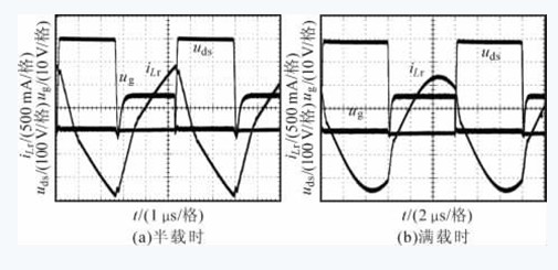
Figure 4 Switching tube ug, uds and iLr waveforms
The efficiency curve of the prototype is shown in Figure 5. It can be seen that the fs variation range is chosen to be 80~150 kHz, and f1 is chosen to be 60 kHz. The efficiency of the prototype is high, and the efficiency of the whole machine reaches 95.5%~97.2%.
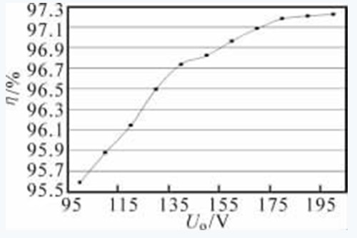
Figure 5 Efficiency curve of half bridge LLC
5 Conclusion
The design method of constant current wide range output LLC resonant converter is introduced. It is pointed out that it has different considerations from the traditional constant pressure LLC design, and the influence of each design parameter is analyzed. For LLCs with a wide range of outputs, the operating range should be designed in areas where the switching frequency is higher than the resonant frequency and the DC gain is less than one. The experiment proves that the efficiency is higher than 95.5% in the whole load variation range. The design method is more suitable for small current output occasions, and the sample output current is 0.7 A. If it is a large current output, the LLC switch tube in continuous state is turned on. The loss and diode turn-off loss have obvious effects and the efficiency will decrease.
008615081129555 south africa candles market is very big market .and 68g 65g 58g candles 6x25 packing are popular .
the white color candles made of 100% paraffin wax ,color is pure white .very strong .we aslo supply color candles .red yellow green blue .black color candles .you can choose .
welcome to visit my factory .
any candles inquire pls be free to contact with Me /ANGEL
South Africa Market Candle,South Africa Fluted Candle,South Africa White Candle,Africa Stick Fluted Candle
Shijiazhuang Zhongya Candle Co,. Ltd. , https://www.zycandlefactory.com