A, ABCD line signal: ABCD is the line selection signal, only exists in the dynamic scanning display. ABCD is actually a binary number and A is the lowest bit. If binary representation ABCD signal is used to control the maximum range is 16 lines (1111). For example, the AB signal has a range of 4 lines (11), so only the AB signal can be used for 1/4 scanning. When the line control signal is abnormal, LED display will show misplaced, highlighted or image overlap.
Second, the data signal: used to provide the data required to display the image. There must be a clock signal to coordinate the data to the display point. Generally, the display data signal is separated. If a data signal is short-circuited positively or negatively, the corresponding color will appear bright light. When the data signal is interrupted, the corresponding color display is indefinite.
Third, the CLK clock signal of the LED display: CLK (CK) is the clock signal, provides the shift register and shifts the pulse, each pulse will cause the data to enter or leave a place. The data on the data port must coordinate with the clock signal to transmit data normally. The frequency of the data signal must be 1/2 times the frequency of the clock signal. In any case, when the clock signal is abnormal, it will make the entire LED display screen clutter.
Fourth, STB latch signal: STB (LT) is a latch signal, the role is to send the data in the shift register to the latch, and its data content through the drive circuit to light up the LED display. The latched signal also needs to coordinate with the clock signal to display the complete image. In any case, when the latch signal has an abnormality, the entire LED display screen will be disorganized.
V. EN enable signal: EN is the display enable, N is the ground (GND). Confirm that the interface between the unit board and the control card is the same, and you can connect directly. If they are inconsistent, you need to make the transition lines yourself (convert the order of the lines). The full screen brightness control signal can also be used to show blanking. Just adjust its duty cycle to control the change in brightness. When the enable signal is abnormal, the entire screen appears bright, dark or brightly smeared.
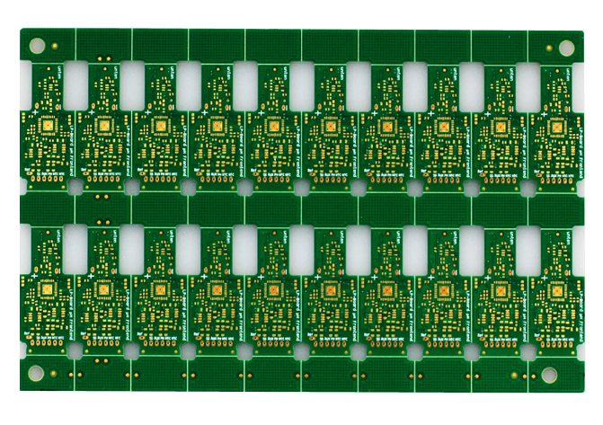
4-layer Medical Treatment PCB Board, Base Material: FR4 TG135. inner/outer copper thickness 1/1.5 oz. Immersion Gold 3U" surface finished. With green colour solder mask and white silkscreen. Board thickness 1.0 mm. Min.line width/Min.line spacing 0.12/0.15 mm. 20-up connect with the routed&v-cut, 100% E-test pass. there are Vias in pad need to be filled with resin and copper cap. Outline Profile tolerance +/-0.1 mm. line width / distance tolerance +/-15%. hole copper 30 um.The medical treatment PCB boards are usually of high precision, strict control of various tolerances required

Medical Treatment PCB Board,Medical Treatment PCB Panel,Medical Treatment Circuit Board,Circuit Board Etching
Orilind Limited Company , https://www.orilind.com