Automotive Grade MCU Market Overview
This article refers to the address: http://
From 2007 to 2011, consumer demand for automotive electronics market products (including MCUs, sensors and body ICs) continued to rise (Figure 1), with MCUs having the largest market share. But in the face of huge market opportunities, automotive electronics manufacturers are also facing challenges. As consumers continue to improve their car comfort, safety, and drivability requirements, car manufacturers have put forward higher requirements in terms of improved performance, increased functionality, and overall cost reduction of automotive electronics, making IC suppliers must improve their systems. Integration to reduce overall system cost and simplify the design process.
MCU's main applications in automotive electronics cover five major areas, namely: 1. Automotive power system control, the main applications are engine control, direction steering and power steering; 2. Automotive control systems, ie body control, mainly including anti-theft control, Switch control, power window control, door control, vehicle light control, etc.; 3, safety control system, including airbags, ABS, SAFF, etc.; 4, driving system control, including instrument panel, air conditioning, chassis control, etc.; Information systems, including entertainment, services, mobile communications, information processing, and GPS navigation. In addition to the high-performance 32-bit MCU for automotive powertrain control and automotive information system control, the other three can use automotive-grade MCUs.
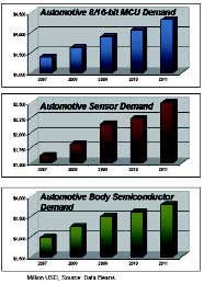
Figure 1 Market demand for MCUs, sensors and body ICs
Silicon Labs' automotive-grade MCU C8051F5XX series is a mixed-signal MCU system that provides high integration, ease of use, and cost-effectiveness for body electronics and point control devices. It is mainly used in control systems such as automatic windows, doors, automatic seats, mirrors, motors, brakes, etc. The C8051F50X family offers a small form factor CAN/LIN network solution that integrates 64K Flash, CAN 2.0B and LIN 2.0 in a 5mm x 5mm package. At the same time, the product integrates a high-precision oscillator with an error of only ±0.5%, which can realize the operation of the CPU without an external crystal or oscillator. The C8051F5XX series has a wide operating temperature range (-40°C to +125°C), which exceeds the automotive electronics's operating ambient temperature requirements (-40°C to +120°C) and is available in 1.8 to 5.25V widths. The voltage range provides customers with a wide range of options in product design.
Figure 2 shows the block diagram of the F500. As you can see from the figure, a complete digital and analog peripheral is integrated in a 5mm x 5mm package. In terms of digital peripherals, including 64K Flash, PWM generator, timer, I2C, SPI interface, and CAN 2.0B and LIN 2.0 controllers. The analog peripherals include a 12-bit ADC, a high-precision internal oscillator with an error of ±0.5%, a temperature sensor, and a comparator. Both the internal reference voltage and the external reference voltage can be used.
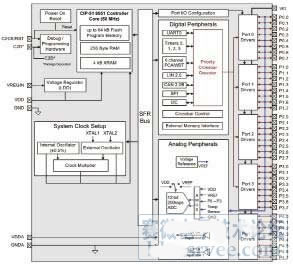
Figure 2 Block diagram of the F500
LIN in automotive electronics
In modern automotive electronics, LIN and CAN buses are indispensable. The LIN bus, also known as the Local Interconnect Network, is an asynchronous, single-wire serial communication bus and a low-cost solution commonly used in automotive electronic networks. The LIN bus consists of a master node and multiple slave nodes (Figure 3), communicating through a single line, and the structure is very simple.
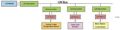
Figure 3 Schematic diagram of the LIN bus structure
There are four main applications of the LIN bus in automobiles: door/window/roof control, steering control, seat control and automotive environmental control.
The characteristics of the LIN bus are: single master-slave structure, each network contains a master node and multiple slave nodes, the master node controls the access of the bus; based on the commonly used USART/SCI interface hardware; the slave controller node does not need quartz or The ceramic oscillator can achieve self-synchronization, thus reducing the hardware cost of the slave node; the signal transmission delay is guaranteed, ensuring the latency of signal transmission under worst conditions to avoid bus access conflicts; low-cost single-wire 12V data transmission The drive and receive characteristics of the line meet the improved ISO9141 single line requirements; the transmission speed can reach 20 kbps.
Silicon Labs' C8051F50x/51x LIN bus hardware interface is compatible with the LIN2.0 protocol, and its high-precision internal oscillator allows the master and slave controllers to operate without the need for an external crystal. The baud rate can be automatically detected in slave mode, and the hardware structure with interrupt error detection and sleep function can achieve low power consumption.
CAN in automotive electronics
CAN (Controller Area Network) is an asynchronous, differential serial bus communication standard commonly used to connect electronic control units (ECUs). In modern automotive electronics, because LIN is less expensive than CAN, CAN is often used to connect communication between various functional modules in ECUs and automotive electronics, while LIN is mainly used for communication between functional modules and their underlying nodes. Thereby reducing costs. The original CAN agreement was created by Robert Bosch GmbH and later adopted by the Society of Automotive Engineers as a universal standard.
CAN is widely used in automotive electronics. It can be used not only in some areas of LIN applications, such as door/window/roof control, direction control, seat control, environmental control, etc., but also for more zeros. In the boundary system, such as transmission system, anti-lock braking system, steering device control, fuel injection system, etc.
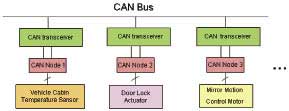
Figure 4 Schematic diagram of the CAN bus
The CAN bus has the following features:
Flexibility - All nodes in a CAN network can receive and send data.
Latency Guarantee - Calculating transmission time and response time is part of the CAN network design.
Data Consistency - All nodes in a CAN network can receive or reject a message.
Powerful error detection function - ensure data integrity through various means such as bit monitoring, cyclic redundancy check, bit stuffing, and message format check.
Fault Definition - Faulty nodes will be cut off to prevent deeper networks from being affected.
Fault Tolerance - The CAN transceiver supports shorting or grounding one of the pins without affecting the message.
High throughput - up to 1Mbps data transfer rate.
In the CAN interface hardware of Silicon Labs C8051F50x/51x series, all CAN control registers can be directly stored; with dedicated CAN interrupt; built-in high-precision oscillator, no external crystal oscillator required; at the same time, the official Bosch module is convenient Customer use.
Automotive electronics solutions with F500 and F30
Option 1 - main window lift controller
As can be seen in Figure 5, there is a master node in the system, which is composed of the F500 MCU as the main controller and contains three slave nodes, which are implemented by using the lower performance F30. The function of the solution is to control all the windows of the car through the driver's side window controller, and at the same time, an anti-pinch algorithm is distributed on each slave node, and there is a resistance sensor and window on each door. The position sensor, the module of the electric window receives the signals of the two sensors to determine whether an object hinders the rise of the window. If the judgment result is "Yes", the power window control module reverses the drive motor so that The window is lowered to prevent pinching.
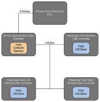
Figure 5 main window lift controller
Option 2 - Automatic seat adjustment
The scheme (Fig. 6) is implemented by the F500 as the master node and the five F30 nodes, and the judging function, the protection function and the intelligent algorithm are distributed on each slave node to realize the normal operation of each module.
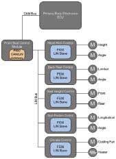
Figure 6 automatic seat adjustment program
Question and answer selection
Q: What are the same and different points between CAN and LIN bus?
A: LIN is a low-cost auxiliary bus for CAN. The speed of CAN can reach 1M and LIN can only reach 20K. Therefore, CAN can be used for high speed systems, and LIN can only be used for low speeds. And generally in automotive electronics, CAN is used to connect the ECU to the control module, while LIN is used to connect the communication between the module and the functional node.
Q: What is the main difference between LIN peripherals and UART0?
A: The serial transmission of the LIN bus is done on a single line, and the UART0 is communicated via a two-wire TX/RX.
Q: After the system clock is switched to the external clock, should the internal clock be turned off?
A: The main clock needs to be turned off.
Q: The serial transmission of the LIN bus is done on a single line. How efficient is the data transmission?
A: All are determined by the main controller, the user can set the priority in the program.
Q: Can you talk about the performance comparison between CAN bus and MIC bus?
Answer: The MIC bus is a time division multiplex bus that transmits data in the form of dual redundant serial communication, which is more suitable for occasions with frequent spike interference. CAN can be simply understood as a differential signal and has a strong ability to suppress common mode interference such as surges.
Q: How do slave nodes of the LIN bus synchronize?
A: All nodes are controlled by the master node, and synchronization is done automatically by the F500's LIN controller.
Q: Can you introduce the main encryption methods of the current MCU?
A: There is an encrypted byte in the Flash of the MCU, and each bit of this byte corresponds to the encryption of one page. When there is no encryption, this byte defaults to "FFH". When you want to encrypt a page, you only need to write the corresponding bit: "0". Once "0" is written, the corresponding space cannot be read or written from outside by some tools. In addition, FLASH can be encrypted using the MCU's own FIRMWARE without affecting access to the encrypted space.
Q: How big is the user's maximum program code?
A: The maximum is 4K bytes.
Q: What should I pay attention to when switching the external crystal?
Answer: When switching the external crystal oscillator, it is necessary to pay attention to: First, to determine the steady state of the crystal oscillator, and second, to determine the switching procedure between the crystal oscillators.
Q: Can the system clock be switched at any time in the program?
A: The system clock can be switched in real time in the program. This feature is useful for low power designs. When high speed operation is required, the internal high speed clock is used; when low speed operation is required, switch to the external clock to save power (the external clock uses a low speed clock).
Q: When the MCU is in RF control, the clock (crystal oscillator) and data line of the MCU will radiate the fundamental frequency or the frequency multiplier of the fundamental frequency. After being amplified by the low-noise amplifier LNA, it will enter the mixing frequency, and the Spur in the band will not be filtered out. Is there a good solution?
Answer: When designing the PCB, separate the data line and the RF line from the ground and try to put it farther. Also, do not wire in parallel.
Q: Does car ignition have an impact on the MCU? How to eliminate this effect?
A: Car ignition will cause relatively large interference, which will affect the work of the MCU. To reduce this impact, it needs to be handled in terms of hardware and software. In terms of hardware, this effect should be fully estimated at the time of design, and appropriate measures should be taken to reduce this effect; in terms of software, some anti-interference processing can be done. The C8051F MCU integrates two protection functions on-chip: low voltage detection and system clock loss detection. When the MCU's Power Supply voltage and system clock are abnormal, the MCU will be forced to reset, thus protecting. It is highly recommended that these two features be enabled when designing with the C8051F MCU.
32V Dc Power Supply is applicable to electrical equipment testing sector. The output current for 1U unit and 2U unit is up to 50A and 200A respectively.
It also covers 12V Dc Power Supply, have the features including high precision and resolution,high efficiency low ripple ,complete multiple protection (OVP/OCP/OPP/OTP/SCP), Master/Slave Series/Parallel modes up to 10 units, and multiple communication interfaces,which allow a more flexible and convenient use of the Programmable Power Supply.
Some features of the DC Power Supply as below:
- Ultrafast respond time
- Accurate voltage and current measurement capability
- Constant Power and wide range of voltage and current output
- Equips with LIST waveform editing function
- Compliant with SCPI communication protocol
- Built-in standard automobile electrical testing curves
- Support RS232/RS485/LAN/USB (standard) ,GPIB (optional)
- Voltage drop compensation by remote sense line.
- Have obtained CE,UL,CSA,FCC.ROHS
32V Dc Power Supply,Adjustable Dc Power Supply,Switching Power Supply,Computer Power Supply
APM Technologies (Dongguan) Co., Ltd , https://www.apmpowersupply.com