In this application note we will compare active and passive biasing circuits for digital potentiometers. Device performance considerations are reviewed. The article also provides the equations necessary for the designer to make the right trade-offs in consumer products.
Volume Controls and Digital PotentiometersThe circuit below illustrates some of the terminology used in this article. We will be focusing on a single-supply application, which is the most common situation in battery- or wall-adapter-powered products. In a single-supply application all parts of the system are powered with VDD and ground, and signals swing between VDD and ground. Capacitors may be used between stages or they can be eliminated for cost and performance reasons.
The wiper buffer reduces the current through the array of switches to improve their distortion performance. This article explores how the bias generator affects the circuit's performance.
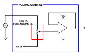
Figure 1. Volume control fed by a signal source.
A digital potentiometer (outlined in red) is an array of switches and resistors controlled by logic that emulates a mechanical potentiometer's sliding contact wiper. A volume-control IC (outlined in blue) is differentiated from the digital potentiometer by the incorporation of two circuits that are very important for best audio performance: the wiper buffer (op amp) and the bias generator (source of VBIAS).
Passive Bias CircuitIf you are using a digital potentiometer and trying to keep cost under control, you can generate the bias voltage with a passive resistive divider as shown in Figure 2. The resistor values ​​are typically equal in value to set VBIAS at the midpoint of VDD and ground. To reduce the AC impedance at VBIAS and clean up any noise, most designers will also add a bypass capacitor, C2.
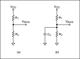
Figure 2. Passive bias circuit.
Mono Volume-Control CircuitLet us take a look at how the chosen circuit values ​​will affect audio performance. The source impedance of the bias circuit, sometimes called the "stiffness" of the supply, is calculated from Figure 3.
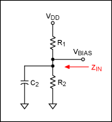
Figure 3. Stiffness is related to the impedance looking into the bias network.
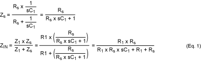
As a check, note that at DC (s = 0), the equation reduces to the impedance of the resistors R1 and R2 in parallel. Now we can insert this impedance into the volume-control circuit (Figure 4).
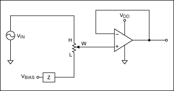
Figure 4. Volume control with finite impedance bias network.
The finite source impedance of the bias network will allow a signal to appear on the L terminal of the digital potentiometer. Setting the wiper to L is supposed to be muted! Instead of seeing no signal, as desired, we will see a divided-down version of the source voltage, VIN.
For example, with the wiper at the L position, a 40kΩ potentiometer, and two 10kΩ bias resistors, we will see an output voltage of:

This is only -19dB below full scale (dBFS) at DC. This means that even if the potentiometer is set to mute, you will still see an output signal.
What happens if we include C2 in the analysis? Let us try a 0.01µF capacitor. The results of Equation 1 are shown in Figure 5.

Figure 5. Passive bias network with a 0.01µF capacitor.
Adding C2 had almost no effect below 1kHz, and the effect at 20kHz only reduces the impedance to 785Ω. We will achieve a mute attenuation of just -34dB, as shown in Figure 5. The capacitor can be raised to 10µF (large) to improve the circuit. At 100Hz we now have a mute attenuation of just -48dB. See Figure 6. This is not even close to the ultimate performance of the volume control, and it is not even close to a reasonable audio specification for mute.
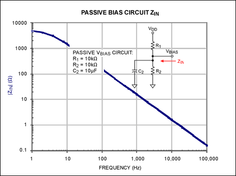
Figure 6. Passive bias network with 10µF capacitor.
Other ProblemsAlthough we have been analyzing this problem at the mute setting (wiper at the L terminal), it is apparent that the finite VBIAS impedance will affect all of the potentiometer settings. The effect will be seen as an increasingly inaccurate attenuation curve as the low end is approached.
How Can the Problem Be Corrected? So, how do we get the impedance down and the mute performance more like 90dB or better? To reach 90dB, we need to be in the single-digit Ohms range.
The values ​​of R1 and R2 can be reduced at the expense of increased DC current. That is not going to be practical. Obviously, we are depending on C2 getting the impedance down very low before the audio band. For 100Hz and 95dB, you find that the capacitor is again unrealistic. For values ​​of 10kΩ, 10kΩ, and a somewhat large 100µF capacitor, the resulting attenuation curve is shown in Figure 7. The solution is to use an active circuit, as will be discussed later in this article.
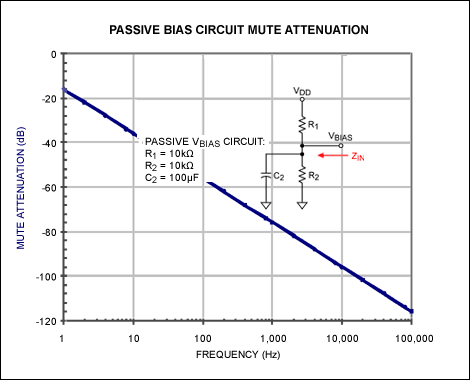
Figure 7. Passive bias network with a 100 µF capacitor.
Stereo CircuitBefore we discuss the active circuit fix, let us take a look at what happens in a stereo design. For a stereo signal that is sharing a passive bias generator, the mute or feedthrough problem occurs. There is, however, an additional problem: crosstalk. Crosstalk is the leakage of signal from the left (L) channel into the right (R) channel, or vice versa. Here is how it happens. When we share the bias line between L and R channels the circuit is as shown in Figure 8.
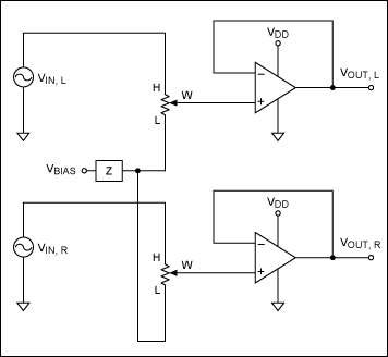
Figure 8. Passive bias networks and stereo signals.
The finite bias impedance again creates a signal voltage on the L terminal of the digital potentiometer when there is an input on the H terminal. However, this time we are sharing the bias generator, so we will get a signal at both VOUT pins from a signal on either the left or the right VIN. The in-channel signal will appear as poor mute attenuation or a failure to follow the attenuation curve. The opposite-channel signal will appear as crosstalk or a loss of stereo separation.
Active Bias There is a solution to all of these problems: provide a very stiff or low-impedance source of VBIAS. A typical circuit is shown in Figure 9. The divided-down VDD is buffered by an op amp whose closed-loop output impedance is fractions of an Ohm. Using this circuit you can achieve results in the 90dB range with careful design.
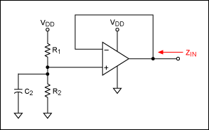
Figure 9. Op amp buffers bias voltage-divider.
Measurement ResultsA test board was used to compare the passive and active approaches. Figures 10 and 11 illustrate typical performance achieved on a MAX5457-based test board for both passive and active circuits. The passive circuit is made of two 1kΩ resistors bypassed by 4.7µF. This results in a pole at 68Hz (calculated) and a continuous 2.5mA drain on the 5V supply.

Figure 10. Full-scale and mute responses with passive biasing of digital Potentiometer.
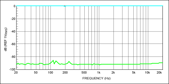
Figure 11. Full-scale and mute responses with active biasing of digital potentiometer.
The active circuit can have higher resistors since only a noninverting buffer is loading it. In this case, two 100kΩ resistors can be used without affecting the active bias curve. This makes the continuous battery drain just 25µA.
Even Better—Integrate It! As we have seen, the passive circuits have poor performance and add both cost and size. An active circuit that creates a buffered version of the resistor-divider works well, but adds the overhead of an op amp. Is there a way to have both small size and the best performance? It turns out that the answer is yes. A volume-control IC like the MAX5486 in Figure 12 is an all-in-one solution that includes this function together with the digital potentiometer in a single package.
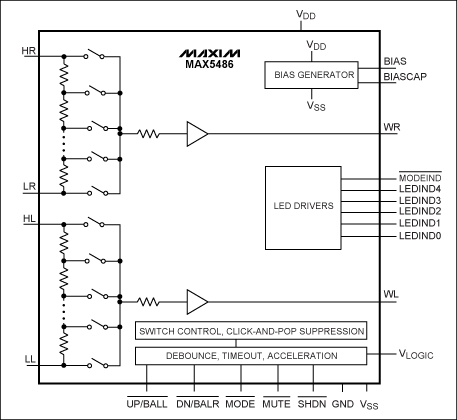
Figure 12. The MAX5486 volume control IC includes VBIAS and wiper buffers required for audio applications.
Various members of the Maxim family of volume-control ICs provide solutions that can be directly interfaced to a microprocessor, pushbuttons, rotary encoders, or even infrared remote controls. Additional features like zero crossing synchronized wiper movements make them optimal for audio applications.
A similar article appeared was published in December 2008 on the Electronic Products Magazine website.
Solar Street Lights are raised light sources which are controlled by solar powered boards commonly mounted on the lighting structure or coordinated into the shaft itself. The sunlight based boards charge a battery-powered battery, which controls a fluorescent or LED light during the night. There are two types of solar light generally in the lighting market which called all in on solar street light and split solar street light.
Features of solar street lights: A modern solar street light has embedded solar panel, inbuilt lithium-ion batteries, battery management system, night and motion sensors as well as automatic controls. The fully automatic device comes with LEDs, inbuilt and replaceable Lithium-ion battery and passive infrared (PIR) sensors. A typical solar street light is weather-proof and water-resistant, has low insect attraction rate and low glare and has a longer life.
Advantages of solar street light:
Environmental protection: solar energy is green, clean and renewable energy. And the widely using of the solar lights can low down the emmision of the carbon dioside.
Cost less to save money: Since the solar lights can be 100% energy, zero electric bill will be paid after the customers install the solar lights. And customers can also save the cost in wire trench.
More easy installation: Does not like electric lights, there is no need wire trench for solar light installation. Everyone can install the solar lights in a very shorten time.
more safe: Solar lights is DC low voltage compared to dangerous 110-220V AC electric power, it does not harm to human.
Solar Street Lights
Solar Street Lights,Solar Walkway Lights,Solar Powered Security Lights,Solar Street Light With Battery
Jiangmen Biaosheng Solar Energy Technology Co., Ltd. , https://www.bsprosolar.com