Experience technology of wireless network construction
Foreword The completion of the wireless project, regardless of the distance and difficulty of the project, is essentially an engineering project. The quality of the project depends largely on the quality of the project. So we must not ignore the problem of engineering installation. The main problems in the project are site selection, installation of antenna feeder, installation of accessories, lightning protection, equipment debugging, etc.
Antenna installation
(1) Antenna location:
The principle of antenna selection is as follows:
1. Visual guarantee: the antenna between the wireless sites should have enough visible space
2. Feeder length: Under the premise of ensuring visibility, try to select the position with the shortest feeder length to reduce loss
3. If you can avoid it, don't install it on the top of the roof
4. Easy antenna installation and construction (2) Antenna assembly:
There are many types of antennas, and each antenna has its assembly instructions. The installation method of the 24dB antenna is given below. Assemble the flow of the antenna. Assemble the two petals together and tighten with 4 small screws.
· Install the small reflecting surface on the top of the feeder rod. Note that the grid with small reflectors must be consistent with the grid with large fans.
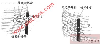
· Pass the feeder rod cable through the fan and L-shaped fasteners and tighten with 4 screws.
· Use U-shaped fasteners and slotted irons to fix L-shaped fasteners on the antenna mast.
· Connect the N-shaped head (male) at the end of the feeder to the N-shaped head (female) of the cable.
· Use omnidirectional firmware to fix the antenna on the mast when installing the omnidirectional antenna.
Antenna debugging · Install the antenna according to the antenna assembly instructions.
· Install the antenna in the highest possible position.
· Connect the Coaxial Cable to the central AP.
· Connect the coaxial cable to the remote WB or SA.
· Manually adjust the antenna until the WLNK light of WB or SA is on.
· Adjust the antenna so that the signal quality of the device lights until the best signal is obtained.
· Determine the general direction of the antennas on both sides. Do not tighten the screws first; (assuming that one side is antenna A and the other side is antenna B) First fix antenna A first, adjust antenna B first, and turn antenna horizontally, according to the indicator on the device panel To find the best receiving position; keep the best receiving position unchanged, then adjust the antenna A, and adjust the antenna repeatedly until the three signal quality lights are on.
· Take 24dBi directional antenna as an example
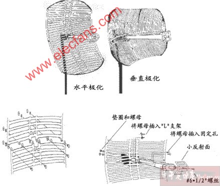
1. Assemble the two fan surfaces and fasten them with 4 # 8-32 machine screws
2. Fix the small reflecting surface on the feed with # 61/2 "screws
3. Fix the feed to the "L" bracket with screws
4. Use "U" shaped clip to clamp the pole and adjust the pitch angle of the antenna with the help of the inclined groove
(3) Antenna debugging:
· Determine the general direction of the antennas on both sides. Do not tighten the screws first; (assuming that one side is antenna A and the other side is antenna B) First fix antenna A first, adjust antenna B first, and turn antenna horizontally, according to the indicator on the device panel To find the best receiving position; keep the best receiving position unchanged, then adjust the antenna A, and repeatedly adjust the antenna until the signal quality light is on to the best.
(4) Selection factors of antenna position
The debugging of wireless engineering in the outdoor part is mainly the debugging of the antenna. The debugging of the antenna is mainly the adjustment of the angle (horizontal and pitch angle). Adjust the antenna, according to the debugging tools provided by various devices, to make the signal quality of the device until the best.
Antenna debugging process · Install the antenna according to the antenna assembly instructions.
· Install the antenna in the highest possible position.
· Connect the coaxial cable to the center equipment.
· Connect the coaxial cable to the remote device.
· Manually adjust the antenna until the debugging equipment indicator is the best.
· The shortest distance between two points. The highest level.
· The best visual effect. Convenient place to install and maintain equipment.
· The separation distance between the antennas is the largest (in diversity reception).
· The nearest place of antenna and equipment. The minimum feeder required.
· Easy to install and maintain.
Feeder production Feeder production is a very important step in a wireless project. Except for DS11 equipment, basically no feeder production is required, and other equipment will inevitably produce a feeder.
Feeder erection and joint production:
The feeder usually adopts 1/2 inch RF cable of American Andrew company, and the loss of this cable is 12.8dB / 100m.
The main considerations when setting up are:
1. Do not bend too much, causing the inner conductor of the feeder to break 2. When the feeder enters the room, it should be bent into a U shape to prevent water from being poured back.
We are now using Andrew's joints, and the manufacturing methods are explained, but we have summarized a more concise method, which requires fewer tools.
Lightning protection and grounding When the feeder system is struck by lightning (or has a high-voltage magnetic field) on the day, do not enter the system equipment. By grounding, the surge can be released in time to ensure the safety of the system equipment and work. We then prepare to introduce several common methods of lightning protection:
1. The lightning rod is used to elevate the lightning strike by erecting a lightning rod next to the antenna. The lightning rod is a good conductor higher than the antenna. When the lightning strikes, it will be led away by the lightning rod. The lightning rod needs to be well connected to the ground, and the grounding resistance is less than 4 ohms. 2. The lightning arrester is connected to the lightning arrester in the feeder system. When the feeder is struck by lightning on the same day, it will be disconnected from the device in time when the lightning strikes. After the current is discharged through the grounding wire connected to the arrester, the connection is automatically restored. The ground wire of the feeder requires a ground every 20 meters, so when the ground wire is less than 20 meters from the feeder head, it can be grounded near the ground wire.
Arrester installation · The arrester is installed between the feeder and the equipment, and the ground wire is drawn from the arrester and connected to the ground electrode. The grounding resistance of the ground electrode requires less than 4 ohms, and the connection must be firm to ensure reliable discharge when struck by lightning.
· Both ends of the arrester are N-type connectors. We need to consider the choice of connectors when making feeder connectors.
Q1: Does WLAN affect human body?
Because the transmission power of WLAN is much weaker than that of mobile phones, the transmission power is about 60 ~ 70mW, and the mobile phone is about 200mW, and the use method is not like the mobile phone directly contacts the human body, so there is no safety consideration.
Q2: Will using WLAN interfere with or affect the operation of other devices?
Basically, the frequency band used by the wireless network belongs to the high frequency range of ISM 2.4GHz, and it does not interfere with electrical appliances used in daily life or offices. Due to the large frequency difference, and the wireless network itself has 12 channels for adjustment, natural Don't worry about the phenomenon of interference.
Q3: What is the ability of the wireless network to penetrate the wall?
It is impossible for general radio waves to pass through the wall, even for general X-rays. The signal can be transmitted through the wall not because the signal passes through the wall, but the signal is reflected many times in the room from the door or the window.The radio wave can pass through the wooden door. Iron gate, and there is no gap, radio waves can never be transmitted
Q4: Factors affecting wireless LAN performance
Transmission power: The transmission power of wireless AP is mostly below 100mw, and the current maximum bridge power (250mw)
Antenna type and direction
Noise and interference: authorized users, microwave ovens, intentional interference, etc.
Building structure: triggering multiple paths, penetration effects, etc .;
Location of wireless access point
In the recent years, with the development of our national economy and basic establishment, more middle buildings, high buildings and super high buildings distribution have been built up. Owing to the increase of the complexity and capacity of distribution among modern buildings, stability and economic requirement to mainline of distribution are getting higher and higher. In order to satisfy the market requirement, we consulted international and national relevant information, and under the direction of relative expert, we researched and developed Branch Cable (pre-made branch cable).The product was tested by the authorization dept. of national wire & cable -National quality supervising & testing center for cable and wire and antiflame construction material. All the technical functions are up to the enterprise standard requirements.The main function exceed JCS376 Japan Standard Requirement of [With Branch Cable". It is mainly suitable for power supply units and controller switching equipment transmitting electricity with 1000V rated voltage and below in middle and high building, industrial and mining unit, enterprise unit and institution. The product has the advantages of safe and reliable power supply, excellent insulating performance, convenient construction and installation, low cost of distribution, wide application scope, wide arrange of varieties and specification, and low requirements of installation environment. In foreign advanced countries, cable with branch has been widely applied to replace the transmission method of bus slots. Compared with bus slots, the product has the additional functions of anti-vibration, water proofing, and flame-resistance, which avoid troubles of installation and maintenance of bus slots.
Branch Cable
Branch Cable,Branch Power Cable,Pvc Sheathed Branch Cable,Insulation Branch Cable
Huayuan Gaoke Cable Co.,Ltd. , https://www.bjhygkcable.com