If you've ever studied PLC programming, you know that it's essential to first grasp the basics of traditional relay control before diving into PLCs. Drawing an electrical schematic is a common starting point. As you progress, you can translate elements like normally open and normally closed contacts, timing functions, and more into ladder diagrams used in PLCs. However, despite these similarities, there are key differences between the two systems. The main distinction lies in their control method: PLCs operate in a serial manner, while relay controls function in parallel.

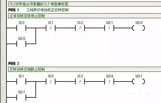
The images above show an electrical schematic for a motor’s forward and reverse operation along with its corresponding Siemens PLC ladder diagram. Comparing the two reveals important differences. In relay-based control, when a start button is pressed for normal rotation, the normally closed contact might not always fully disconnect before closing again. This is because the relay circuit operates in parallel, meaning all components are powered simultaneously. In contrast, a PLC reads and executes instructions sequentially, which means the control logic is processed one step at a time. This fundamental difference affects how signals are interpreted and executed in each system.
Understanding this distinction is crucial for anyone working with industrial automation. While both systems aim to control electrical devices, their underlying mechanisms lead to different behaviors. For example, in a relay system, multiple contacts can be activated at once, but in a PLC, the order of execution matters. This makes PLC programming more precise, especially in complex applications where timing and sequence are critical. As you continue learning, you'll find that mastering both the relay logic and the PLC ladder diagram will give you a solid foundation in industrial control systems.
Digit Segment Led Display,Washing Machine Display,Smd Led Display,Bar Segment Led Display
Wuxi Ark Technology Electronic Co.,Ltd. , https://www.arkledcn.com