If you've ever worked with PLC programming, you'll know that it's essential to first grasp the basics of traditional relay control before diving into PLCs. Drawing out an electrical schematic is a common starting point. As you study, you can translate elements like normally open and normally closed contacts, timers, and other components from the relay diagram into a PLC ladder diagram. However, despite these similarities, there are fundamental differences between the two. The main distinction lies in their control methods: relay circuits operate in parallel, while PLCs use a serial processing approach.

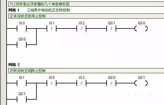
The diagrams above illustrate a motor’s forward and reverse control circuit using both a traditional relay system and a Siemens PLC ladder diagram. Comparing the two reveals key differences. In a relay-based system, when a start button is pressed, the normally closed contact may not always break and then re-close properly, especially under high-precision conditions. This is because the relay circuit is powered in parallel, meaning all components are active at the same time. In contrast, the PLC ladder diagram operates sequentially—each rung is scanned one after another, which leads to a different behavior in the control logic. Understanding this difference is crucial for designing reliable and efficient PLC programs.
One Digit Led Display,Two Digits Led Display,Three Digits Led Display,Four Digits Led Display
Wuxi Ark Technology Electronic Co.,Ltd. , https://www.arkledcn.com