In this paper, we conduct a detailed analysis and modeling of the semiconductor laser temperature control circuit used in communication equipment. From an automatic control perspective, we evaluate the performance metrics and test the design of the temperature control circuit. By simulating various control methods and comparing the measured data, we identify a more efficient temperature control circuit that meets the requirements of general temperature control systems.
In the field of fiber-optic communications, semiconductor lasers are commonly used as light sources. The emission wavelength of these lasers is closely related to the temperature of the die. A temperature increase typically causes the wavelength to shift longer, approximately 0.1 nm per degree Celsius. For standard single-wavelength systems, this drift has minimal impact on system performance. However, in Dense Wavelength Division Multiplexing (DWDM) systems, where channel spacing is already very narrow, maintaining stable wavelength is crucial. For instance, a 32-channel system operating in the C-band has a channel spacing of about 100 GHz (0.8 nm), while a 160-channel system in the C+L band has a spacing of 50 GHz (0.4 nm). Without proper temperature control, even small temperature changes can cause the entire system to fail. Moreover, semiconductor lasers are highly sensitive to temperature, with their threshold current, output wavelength, and optical power all being affected by thermal variations. Their operational lifetime is also strongly dependent on their working temperature.
Experiments have shown that the lifetime of a laser can decrease by an order of magnitude for every 30°C increase in temperature. To meet high reliability standards and ensure long-term performance, it is essential to control the die temperature. This necessitates the use of an automatic temperature control (ATC) circuit within the system.
**1. Principle of Temperature Control System**
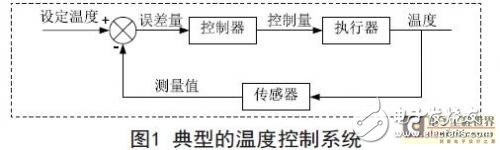
Figure 1 shows a block diagram of a typical temperature control system. The sensor compares the actual temperature with the set value, generating an error signal. This signal is sent to the controller, which drives the actuator to adjust the temperature. The overall purpose of the system is to maintain the temperature at the desired set point.
In optical communication systems, two main types of light sources require temperature control: the communication laser and the pump laser. Both typically integrate a thermistor and a thermoelectric cooler (TEC) into the temperature control circuit to enable cooling or heating as needed.
The peripheral circuit must amplify the temperature detection signal and process it through a controller circuit. The power amplifier then drives the TEC to complete the temperature regulation process. Therefore, the key components of the temperature control circuit include: the temperature signal detection and amplification circuit, the controller circuit, and the power amplification circuit.
**2. Establishment of the Thermal Model**
A common structure involves mounting the laser, backlight, and thermistor on a sub-heat sink, which is then fixed to a TEC cooler. When the temperature control system operates normally, the sub-heat sink remains at a constant set temperature. Depending on the polarity of the current applied to the TEC, it can either cool or heat the component. The temperature change is gradual, whether in a cold or hot state, rather than abrupt.
At a given current, after sufficient time, the external heat exchange reaches equilibrium, and the temperature stabilizes at a certain value relative to the casing. This behavior suggests that the TEC acts similarly to a first-order inertial link in the transfer function model.
To determine the parameters Ktec and Ttec, a constant current is applied to the TEC, and the temperature is monitored using a thermistor. The relationship between temperature and time is plotted to obtain the corresponding curve.
For example, with the FLD5F6CXF laser from Fujitsu, after measuring Ttec for 6 seconds, Ktec was found to be approximately 90, indicating that a 1 A current produces a temperature difference of around 90°C. However, due to the distance between the TEC and the temperature sensor, a thermal delay must be considered. In the case of the Fujitsu laser, the measured thermal delay was about 100 milliseconds. This delay introduces an additional time lag into the control loop, effectively adding a delay element to the system.
Optical Filter,Long Wave Pass Filter,Optical Pass Band Filter,Bandpass Filter
Danyang Horse Optical Co., Ltd , https://www.dyhorseoptical.com