LCR Tester Usage Diagram
1. Start by preparing the LCR tester. The white button on the front panel is the power switch. Make sure the device is connected to a stable power source and turned on before proceeding.
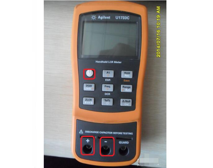
2. The main measurement function can be changed using the ZLCR button, while the DQe button allows you to switch between auxiliary functions. This helps in selecting the right mode for your specific testing needs.
3. Prepare the necessary peripheral connectors. These include test leads, clips, or any other accessories required to connect the components under test to the LCR meter.
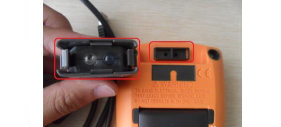
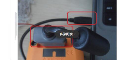
4. Connect the LCR tester to the computer as shown in the diagram. A USB or serial cable is typically used for this purpose, depending on the model of the tester. Ensure that the connection is secure and the software is properly installed.
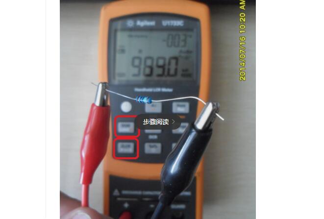
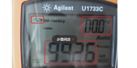
5. Once the setup is complete, the measured data will appear on the tester’s screen. This includes parameters such as impedance (Z), inductance (L), capacitance (C), resistance (R), and more, depending on the selected mode.
6. You can now start the measurement process. Make sure all connections are correct and the settings match the component being tested.
How Can the LCR Tester Correct Errors?To ensure accurate measurements, the LCR tester offers several correction functions. These corrections are essential because the accuracy of the readings depends on factors like frequency, impedance range, and the test setup. Performing a full calibration across all ranges can be time-consuming, but it's crucial for high-precision applications.
Two common correction methods are zero-point correction and load correction.
Zero-Point Correction: This is used when the zero drift of the tester affects the results significantly. Zero drift can vary based on the cable configuration and electrode spacing. Therefore, it's important to perform the zero-point correction using the same wiring and electrode setup as during actual measurements. This ensures that the baseline is accurate before starting the test.
Load Correction: In addition to zero drift, other errors may occur due to the measurement fixture or environmental conditions. Load correction helps improve accuracy by compensating for these errors. Even if the LCR tester doesn’t have a built-in load correction feature, you can manually calculate correction factors for different frequencies and impedance ranges using known standard components.
To perform load correction, first, conduct a zero-point correction. Then, measure a standard impedance with a known value (Zstd). If the measured value is Zms, the correction factor can be calculated using the formula: Correction Factor = Zstd / Zms. This factor can then be applied to subsequent measurements to improve accuracy.
By following these steps, you can ensure that your LCR tester provides reliable and precise readings, making it a valuable tool for electronic testing and component analysis.
ZTTEK Electric Scooter Batteries. Any size batteriesb can be customized! Suitable for most electric vechile modles, like electric e-bike, golf cart,forklift,beach electric motorcycle.
Electric Motorcycle Battery,Li-Ion Battery Pack For Electric Bike,Lithium Battery Charger For Electric Bike,Lithium Battery Pack For E-Bike
Jiangsu Zhitai New Energy Technology Co.,Ltd , https://www.zttall.com