Designers often find op-amp datasheets confusing because not all performance parameters are specified with clear minimum or maximum values. In some cases, you might have to rely on "typical values" found in the specification table or in typical performance graphs. But what exactly does "typical value" mean? How much can it vary under different conditions?
This is a complex question, as the meaning of "typical" can vary depending on the specific parameter being discussed. To help clarify, we'll break down three common characteristics that often raise questions:
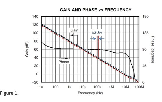
Bandwidth – The gain-bandwidth product (GBW) of an op-amp is mainly determined by the input stage current and internal compensation capacitance. These factors can lead to variations in GBW of around ±20%. While this range may seem large, selecting an op-amp with a larger margin can make it easier to design for a wide range of bandwidths. If needed, feedback components can also be used to control the closed-loop bandwidth of your circuit. Keep in mind that these variations appear relatively small on an open-loop gain/phase plot (see Figure 1).
Slew Rate – Similar to bandwidth, the slew rate is influenced by internal current and capacitance. As a rule of thumb, it's usually safe to choose an op-amp with a slew rate that is 20% higher than the minimum required. In critical applications, you may want to add more margin to account for unexpected conditions. Most applications don’t push the amplifier to its maximum slew rate, so this approach is generally acceptable.
Voltage Noise – The wideband or flatband voltage noise of an op-amp is mainly determined by the current in one or more input transistors. Higher currents reduce noise in a square-root fashion. Therefore, a 20% change in current can result in approximately a 10% change in flatband noise density (see Figure 2).
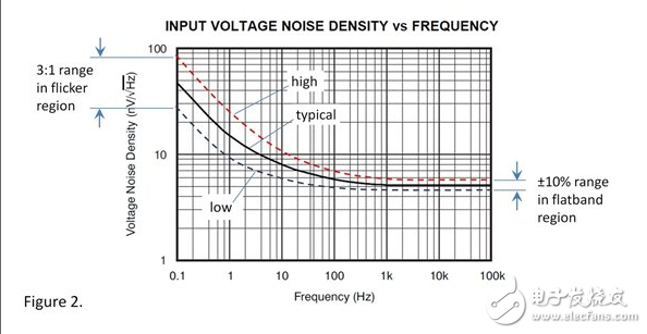
Low-frequency 1/f noise – Also known as flicker noise, this type of noise behaves differently and can vary significantly. The amplitude of 1/f noise can differ by up to 3:1, and the difference between JFET and CMOS fabrication processes can be even more pronounced. This noise region is particularly important for low-frequency applications, where it defines the peak-to-peak noise level over a range like 0.1 Hz to 10 Hz.
While there are general guidelines, it's difficult to define exact ranges of variation due to differences in amplifier design and manufacturing processes. However, even partial information can be valuable, and most designs are well-suited to handle these estimated variations.
The appropriate margin for your application depends on the type of device you're working on and the testing procedures you perform. Understanding the gap between specifications and real-world performance helps set realistic design goals. This kind of engineering judgment is essential for successful analog design.
24V Frequency Transformer,110V 60Hz To 220V 50Hz Transformer,Oil-Filled Electric Transformer, electronic oiled transformer
IHUA INDUSTRIES CO.,LTD. , https://www.ihuagroup.com