GPS / GSM Car Anti-theft Alarm System Design
Abstract: Using GPS / GSM technology to develop car anti-theft system. The system uses GPS positioning technology to obtain the location of the vehicle, determine whether the vehicle is moving, and can send the vehicle location information to the user through the GSM network. Users can set the working status of the system through the GSM network. The internal control of the system is completed by the single-chip microcomputer, which receives GPS data and commands from the user and gives corresponding processing after analysis. The positioning accuracy of the system is within 10 meters, which can notify users in time after the vehicle is stolen, and more functions can be added after expansion.
O Introduction With the popularity of vehicles such as automobiles, wireless communication technology and global satellite positioning (GPS) technology have gradually begun to be applied to vehicle monitoring and other fields. Whether it is the monitoring of special vehicles such as police cars and banknote transporters or the anti-theft monitoring of ordinary cars, wireless communication and GPS technology play an important role. At present, the main mobile wireless communication methods are: a. Cluster mobile communication method; b. DSRC (Dedicated Short Range) communication method; c. GSM (Global System for Mobile Communications). Among them, the GSM mode has a large data range, good data confidentiality, convenient use, and low cost. Combined with the GPS system, the GSM system can transmit the vehicle's position, speed, driving direction, and other status information to the owner's handheld terminal or monitoring center through a wireless communication link to monitor the vehicle.
Among the services provided by the GSM system, the voice service and the data service need to establish a connection through dial-up, and once the connection is established, charging starts. The GSM short message service does not need to establish a dial-up connection, but only needs to send the information to be sent plus the destination address to the short message center, and then the short message center forwards it to the target user terminal. The short message service is charged according to the number of short messages sent, as long as the short message is limited to 140 bytes at a time, this data length is sufficient to transmit GPS positioning information. It can be seen that the use of GSM short message service for data transmission can make full use of the mobile communication network with a wide coverage and realize the positioning of remote movable targets in a cheap way, which is more suitable for the anti-theft monitoring of automobiles. This article uses PIC18F2450 microcontroller, SIRF third GPS receiver module and GSM module TC35i to design vehicle anti-theft monitoring terminal.
1 Car terminal hardware design Car terminal is mainly composed of four parts, namely GSM module, GPS receiver module, single-chip microcomputer control circuit and power supply circuit. The GPS module is responsible for receiving positioning data; the GSM module sends and receives short messages under the control of the single-chip microcomputer; the single-chip microcomputer control circuit analyzes the GPS positioning data and makes corresponding processing according to the user's settings. The power circuit is provided by the 7805 with a + 5V DC voltage for the microcontroller and the GPS module. The LM2941CS then regulates the + 5V DC voltage to + 4.2V for the GSM module. The block diagram of the system is shown in Figure 1.

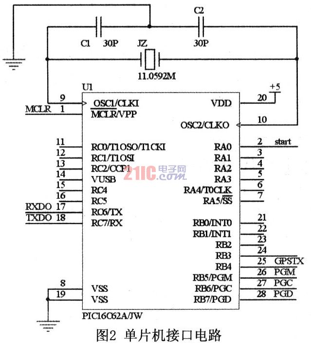
1. One-chip computer control circuit The system chooses PICl8F2450 of Microchip Company as MCU. The chip is a 28-pin high-performance single-chip microcomputer using nanowatt technology, which has the advantages of high reliability, low cost, low power consumption, small size and so on. There are 16k bytes of Flash program memory and 768 bytes of RAM inside, which supports online programming and debugging. There is only one universal asynchronous serial port inside the microcontroller. In order to be able to communicate with GPS and GSM modules at the same time, the microcontroller requires two serial ports. However, if you choose a single-chip microcomputer with dual serial ports, it will increase costs, so this system uses the PICl8F2450 ordinary I / O port and the library function provided by the C language compiler of this series of single-chip microcomputers to design a software serial port. The hardware serial port inside the single-chip microcomputer communicates with the GSM module through pins 17 and 18, and the software serial port receives GPS signals through pin 25. The 2 foot of the one-chip computer is regarded as the start foot of GSM module. The interface circuit is shown in Figure 2.
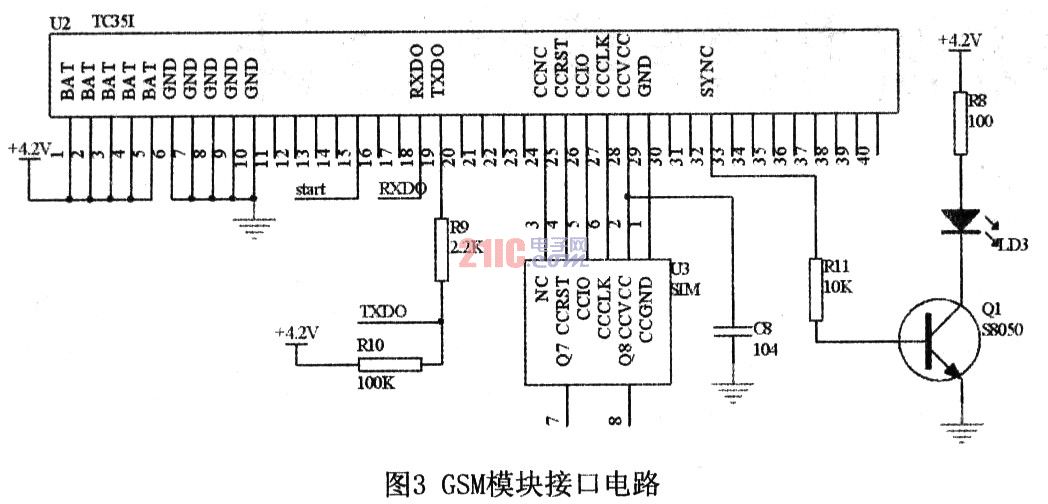
1.2 GSM module The GSM module is responsible for transferring information between the vehicle-mounted terminal and the monitoring user. This system uses German Siemens industrial GSM module TC35i. The TC35i module is an industrial-grade GSM module that supports Chinese short messages. It works in GSM900 and GSMl800 dual frequency bands and can transmit voice and data signals. The data interface (CMOS level) of the TC35i can transmit commands and data in both directions through AT commands. It supports SMS (short messages) in Text and PDU formats, and can be restarted and recovered from failures through AT commands or shutdown signals.
The TC35i module has 40 pins and is divided into 5 categories: power supply, data input / output, SIM card, audio interface, and control. Its working voltage is 4.2V, if the power supply voltage of the module is lower than 3.3V, it will automatically shut down. When the module is transmitting signals, the peak current can be as high as 2A. Therefore, this module has high requirements on power supply. This system uses a switch-type adjustable high-performance microwave circuit dedicated voltage regulator chip LM2941CS, which can provide a large current stable voltage output. When using TC35i module, its start pin IGT must add a low level longer than 100ms to make TC35i hang into working state. The data input / output interface of the TC35i module conforms to the ITU-T RS232 interface standard and supports the standard AT command set.
The interface circuit of GSM module and MCU is shown as in Fig. 3.
1.3 GPS module The GPS module used in this system is SIRF star III, the third-generation high-sensitivity lead-type GPS receiver module of SIRF. The positioning accuracy of the chip is less than 10 meters. The time of cold boot / warm boot / hot boot reaches 42s / 38s / 8s respectively, and can track up to 20 satellite channels simultaneously. There is a rechargeable battery inside, which can save ephemeris data for quick positioning. The serial port data format is TTL level data output, the communication rate is 4800 communication baud rate, and GPS full data is output once per second. The GPS antenna of this module adopts MMCX interface, the data line interface is a 6-wire connector, and the cable is output. It is very simple to use. Only three output wires are needed. The first pin is connected to a DC positive power supply of 3.5 to 5.5V. The fifth pin is the power ground, and the second pin is the GPS output line. It is a serial signal of TTL level. The high level is greater than 2.4V, the low level is less than 0.4V, and the output driving capacity is 2mA. SCM interface; the sixth pin is the second signal output, and every second will output a pulse signal of about 0.2V with a width of 10ms for timing. Because the module only sends data to the microcontroller and does not receive data from it, the microcontroller in this system uses a software serial port to communicate with it. The second pin of the MMCX interface can be connected to the 25 pin of the microcontroller.
2 Car terminal software design
2.1 Reception of GPS positioning data By default, the GPS receiving module SIRF star III outputs positioning data once per second, usually using the simplified GPRMC data format, which includes the longitude, latitude, and speed of the target (nautical miles / hour), Important information such as the direction of movement, year, month, hour, minute, second, millisecond, and whether the positioning data is valid or invalid. The statement format is as follows:
$ GPRMC, <1>, <2>, <3>, <4>, <5>, <6>, <7>, <8>, <9>, <10>, <11>, <12> , * Hh
<1>: represents UTC local time. The format is "hour, minute and second", and the hour, minute and second are two digits.
<2>: represents working status. "A" indicates that the data is available, "V" indicates that the receiver alarms, and the data is not available.
<3>: represents latitude data. The format is "degree, degree, minute, minute. Minute, minute, minute".
<4>: represents the latitude hemisphere, which is "N" or "S".
<5>: represents longitude data. The format is "degree, degree, minute, minute. Minute, minute, minute".
<6>: Represents the longitude hemisphere, "E" or "W".
<7>: represents the ground speed, the range is 000. O ~ 999.9 sections.
<8>: Represents the course to the ground, the range is from 000.00 degrees to 359.9 degrees, the true north is 0 degrees, the east is 90 degrees, the south is 180 degrees, and the west is 270 degrees.
<9>: Represents UTC local time, the format is "Day, Day, Month, Year, Year".
<10-12>: These three data are generally not used.
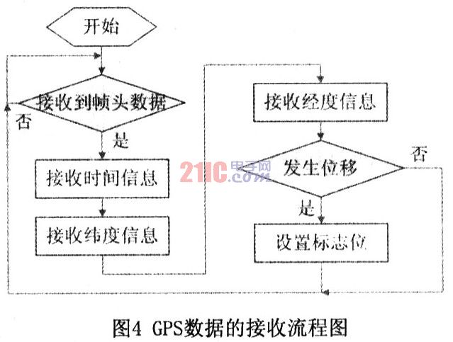
Each piece of positioning data starts with "$" and ends with a carriage return and line feed. The software should realize the function of receiving and analyzing GPS data. The flow chart is shown in Figure 4.
2.2 GSM module control and short message processing SCM can send AT command to control the GSM module TC35i, send text messages commonly used Text and PDU mode, using Text mode to send and receive SMS codes is simple and easy to implement, but the disadvantage is that Chinese SMS ; PUD mode not only supports Chinese mode, but also can send English text messages.
The MCU mainly transmits two types of information through the GSM module: one is to receive the user's setting and request commands, and give a reply after processing; the other is the alarm sent to the user when the MCU determines that the car has moved in the armed state And location information.
The format of user settings and request information is shown in Table 1.

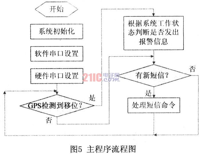
The main program flow chart of the single chip microcomputer is shown in Figure 5.
When the user receives the positioning SMS, the location of the vehicle can be determined. Both S60 and PPC mobile phones support Google mobile maps, such as NOKIA N82, start Google Maps, select the network connection method WAP, enter the received latitude and longitude data, you can locate the vehicle location on the map.
3 Conclusion After testing, this system can achieve positioning within 10m accuracy under the urban road environment, and can provide users with alarm positioning services according to user settings. The system is easy to operate and easy to install. Through the expansion of software and hardware, some other functions can be achieved, such as the function of the system can be expanded by adding a vibration detection circuit to send an alarm message to the user when the car is pryed or hit.
Wall Mount All In One Pc with the monitor and computer in the same metal case, which can attach to a wall by a VESA mount.
The back wall with holes for connecting machine , the standard of wall Mounting bracket is VESA 100*100 mm(length * width) for small size, and 200*200 or 300×300 mm for big one .
Wall screw specifications is M8.
Wall Mount All In One Pc
Wall Mount All In One Pc,All In 1 Computer,Wall Mountable All In One Pc,Allinone Computer
Guangzhou TouchWo Electronics Co.,Ltd. , https://www.touchaio.com