Introduce the basic working principle of Atmel's wireless transceiver ATA5823 / 5824 and its application in short-distance wireless transmission. The system is based on the C805lF530 single-chip microcomputer as the control core. Its built-in A / D converter converts the amplified pressure and strain signals into digital signals, and then transmits it to the ATA5823 / 5824 through the built-in SPI communication module, which is modulated by the ATA5823 / 5824 code. After the transmission; the receiving end is also received and processed by ATA5823 / 5824 and then transmitted to the CPU or computer to achieve short-distance wireless transmission.
With the development of communication and information technology, the application of short-range wireless communication technology has become increasingly mature. Generally, both communication parties only need to transmit information through radio waves and the transmission distance is limited to a short distance (tens of meters). It can be called short-range wireless communication.
ATA5823 / 5824 produced by Atmel is a UHF band short-range wireless transceiver dedicated device, with ASK and FSK two modulation methods, with high receiving sensitivity, low power consumption, high transmission rate, simple peripheral circuit and operating temperature range, etc., available For short-distance wireless transmission systems such as tire pressure monitoring, keyless entry system and remote control, home automation.
1 ATA5823 ï¼ 5824 internal structure and characteristics
ATA5823 / 5824 is a highly integrated multi-channel, half-duplex, full-duplex USK band ASK / FSK transceiver, its internal structure shown in Figure l. The FSK transmission mode uses a frequency synthesizer with N-digit fractional frequency, using direct phase-locked loop modulation, while the ASK transmission mode uses the switch modulation of the power amplifier module; in FSK mode, the transmission rate range of ATA5823 / 5824 is l ~ 20 KBaud; in ASK mode, its transmission rate range is 1 ~ 10KBaud, and its encoding methods include Manchester encoding and two-phase encoding. ATA5824 works in the frequency band of 433 ~ 435 MHz or 867 ~ 870 MHz, while ATA5823 only works in the frequency band of 313 ~ 316 MHz, requiring only few external components.
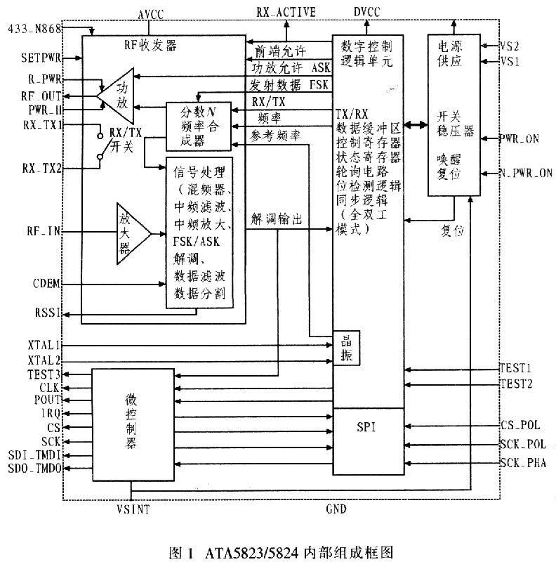
The internal receiving part of ATA5823 / 5824 is a low-IF receiver with high receiving sensitivity. In FSK mode, when the transmission rate is 20 KBaud, the receiving sensitivity is as high as -105.5 dBm, and when the transmission rate is 2.4 KBaud, the receiving sensitivity is -109 dBm; in ASK mode, when the transmission rate is 10 KBaud, the receiving sensitivity is- 111.5 dBm, and when the transmission rate is 214 KBaud, the receiving sensitivity is as high as -116 dBm.
ATA5823 / 5824 adopts QFN48 SMD package of 7 mm × 7 mm, the operating temperature range is as wide as -40 ~ 105 ℃, the power consumption current in low power consumption mode is less than 10 nA, and the working range of power supply is 2.15 ~ 3. 6 V or 4.4 to 5.25 V, suitable for battery-powered occasions. The device has a variety of basic working modes: OFF mode, IDLE mode, TX mode, RX mode, Full dupl-ex mode, etc., and can enter another working mode from one working mode under the instruction control of the microcontroller.
2 SPI interface of ATA5823 ï¼ 5824
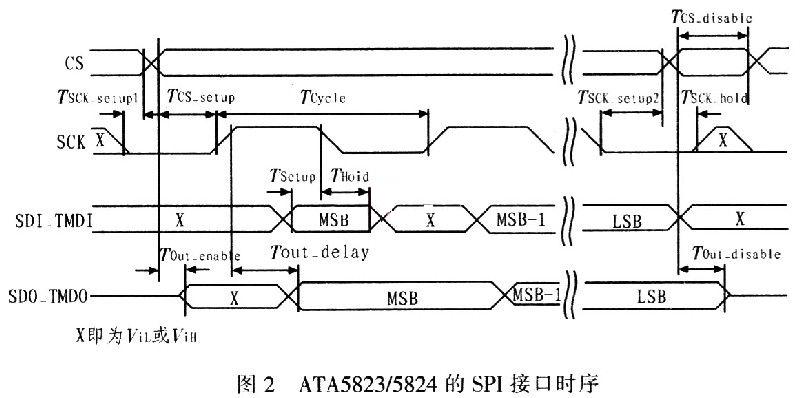
ATA5823 / 5824 are connected to the controller through a high-speed 4-wire SPI interface, which are chip select CS, serial clock SCK, serial data input SDI-TMDI and serial data output SDO-FMDO. The device can change the SPI interface through hardware connection to achieve connection with different types of controllers. For example, when the CS-POL pin is high, the chip select signal CS is active low, and when CS-POL is low, CS is active high.
SCK-POL and SCK-PHA define the polarity of the interface timing and the phase of the SCK signal. According to the high and low levels of these 2 pins, 4 different interface timings can be combined. Figure 2 shows one of the interface timings.
3 Application in short-range wireless transmission
In the field of short-range wireless transmission. The wireless sensor network integrates technologies such as sensors, embedded computing, modern networks and wireless communication, and distributed information processing, and cooperates with various micro sensors to monitor, sense, and collect information on various environments or monitoring objects in real time, and send them wirelessly The information is transmitted to the user terminal in a self-organizing multi-hop network. Due to the wide operating temperature range of ATA5-823 / 5824, it can meet the demanding application requirements of those working environments, so it can be used as a wireless transmission transceiver for short-distance wireless transmission.
Figure 3 (a) and Figure 3 (b) respectively give the structure diagram of the wireless transmission system and the structure diagram of the wireless sensor network module.
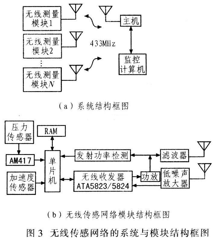
When the system works at 315 MHz, ATA5823 is selected, while at 433 MHz, ATA5824 should be used. In Figure 3 (b), the single-chip computer uses C8051F530. Its working temperature range is -40 ~ + 105 ℃, internally integrated A / D converter, SPI bus interface, temperature sensor, etc .; the pressure sensor uses diffused silicon pressure sensor, and AM417 is the excitation and amplification circuit of the pressure device, its output It is a digital quantity converted by the internal A / D converter of the single-chip microcomputer; the acceleration sensor adopts the BMAl50 type three-dimensional digital acceleration sensor, which can directly output the digital quantity to the single-chip microcomputer; the radio frequency power amplifier uses HMC454ST89, and the transmission power detection uses HMC600.
Transceiver switch is integrated inside ATA5823 / 5824. However, its receiving and transmitting pins are independent. In the application circuit shown in FIG. 4, in order to increase the transmission distance, power amplification is performed after the transmission output, and the receiving and transmitting antennas are separated, but the internal ATA5823 / 5824 is not used. Transceiver transfer switch. The radio frequency signal output from the radio frequency output pin of ATA5823 / 5824 is sent to the corresponding filter after the matching network, and the filtered signal is sent to the power amplifier HMC454. The output after power amplification is divided into two channels by the power divider, one channel is sent to the power detection circuit to monitor the transmission power in real time, and the other channel is sent to the antenna for transmission. In order to facilitate the test, the short-circuit resistors RTA, RTB and RTC should be connected at appropriate positions between the RF output pin and the filter, filter and power amplifier. During debugging, when outputting directly without filtering or power amplifier, just solder a 0 Ω resistor at the position of RTA to send the output signal directly to the antenna; similarly, when only RTC welding, the filtered signal is directly Sent to the antenna, no longer amplified by the power amplifier. It should be noted here that it is better not to solder the unused circuits.
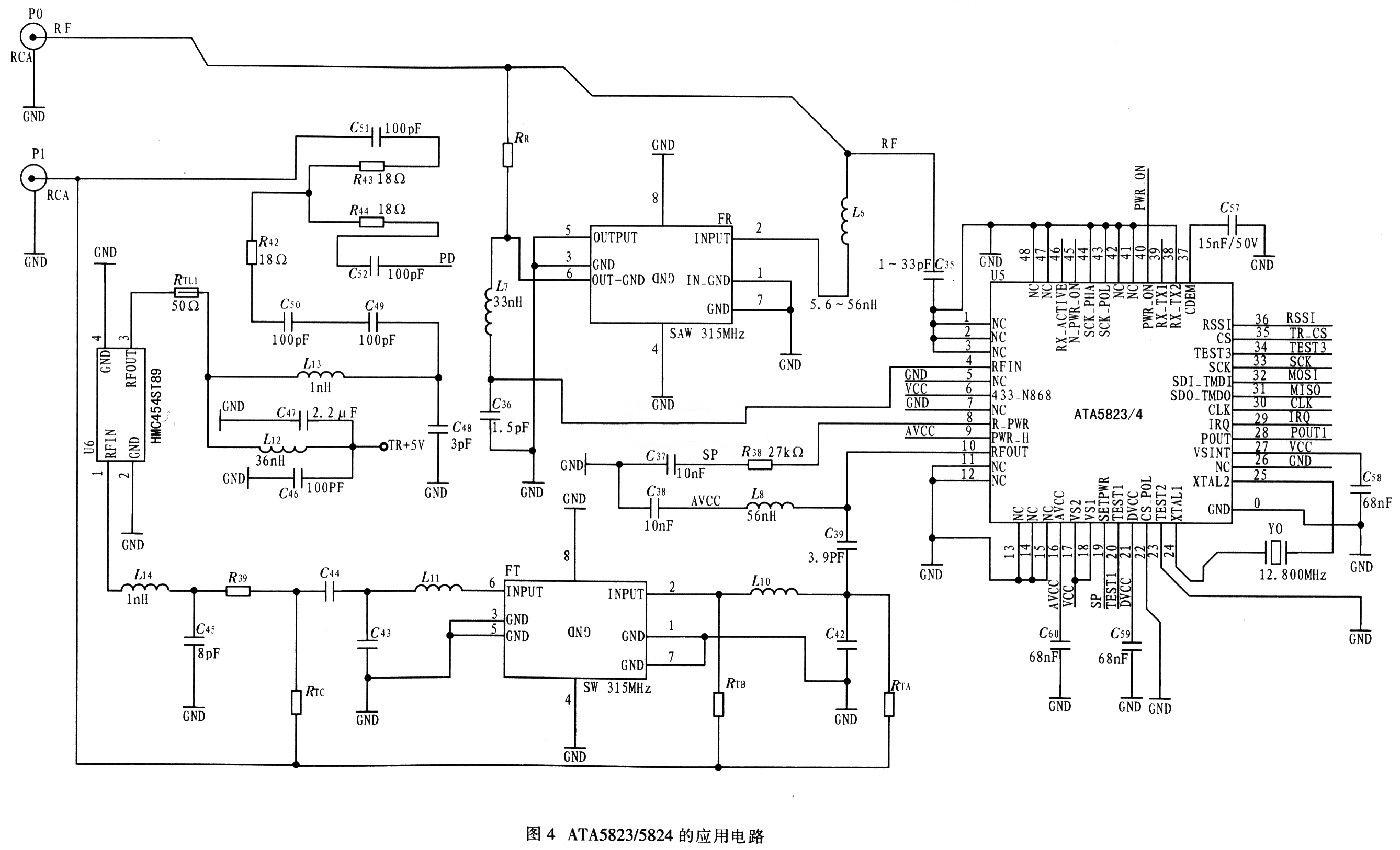
The receiving channel is connected with a resistor RR that has a similar function as that of the transmitting channel RTA. The signal received by the receiving antenna enters the input pin of ATA5823 / 5824 through the matching network and filter. When the receiving channel does not require filtering, the filter may not be welded, and a 0 Ω resistor may be welded at the RR.
The host computer connects to the computer through the RS232 serial port, transmits the collected information to the computer, and at the same time starts the computer monitoring program to control each module.
4 Conclusion
According to the system structure and circuit design scheme, ATA5823 is used to realize the wireless transmission of pressure, temperature, acceleration, strain measurement results, and the transmission distance is up to 20 m. Through the corresponding computer management program designed, it can display the measured data in real time and draw the change curve, and can convert the data to EXCEL file and save. The actual test proves that the wireless transmission module of the system is buried under a half-meter deep wet soil layer, and can still effectively transmit the measurement data, but at this time the transmission distance is only about 10 m. If the transmission protocol is further improved, the application of relay transmission will be able to expand its application.
Babbitt Wire is with tin as the base, the product is added with certain amount of antimony, copper
or other improved elements.
Sn Sb7Cu3 Babbit metal is suitable for metal spraying on the end face of metalized ï¬lm capacitor. With strong adhesive force, good weldability and low loss angle, it is an ideal metal spraying material for laminated capacitor.
Other trade marks are suitable to use CMT, TIG and MIG technology to manufacture sliding bearing bush material layer. It is of high bonding strength with substrate, with material utilization rate of 70~80%. It has small amount of ingredient segregation without any loose or slag inclusion. The internal control standard of the alloy composition is prevailing over GB/T8740-2013. Babbi1 metal added with improved elements can substantially enhance the service life.
Snsbcu Babbitt Wire,Overlaying Materials,Thermal Spray Babbitt Wire,Babbitt Wire
Shaoxing Tianlong Tin Materials Co.,Ltd. , https://www.tianlongspray.com