The TL431 is a crucial component in the feedback loop of switching power supplies (SMPS). It combines a reference voltage with an open-collector error amplifier, making it cost-effective and easy to use. Despite its widespread application, many designers overlook the bias current of the TL431, which can negatively impact system performance.
A simplified schematic of the TL431 is shown in Figure 1. It includes a reference voltage and an error amplifier that drives an NPN transistor. In a closed-loop system, a portion of the output voltage is compared to the internal reference voltage (Vref) of the TL431.
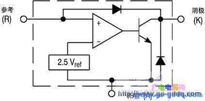
**Figure 1: TL431 Equivalent Circuit**
Another simplified DC model of the SMPS is shown in Figure 2. The output voltage (Vout) is compared with Vref through a resistor divider network. The theoretical output voltage is Vref divided by the feedback factor α. However, the overall gain chain and various impedances affect the actual output voltage, as described in the following equations:
$$
V_{out} = \frac{V_{ref} \cdot \beta \cdot G}{1 + \alpha \cdot \beta \cdot G + \frac{R_{SOL}}{R_L}} \quad (2)
$$
$$
\text{Static Error} = \frac{V_{ref}}{\alpha} - V_{out} = \frac{V_{ref} \cdot (R_{SOL} + R_L)}{\alpha \cdot (R_{SOL} + \alpha \cdot \beta \cdot G \cdot R_L + R_L)} \quad (3)
$$
From equation (3), increasing the gain reduces static error and improves output accuracy. Another key parameter affected by the gain is the output impedance. The system's output impedance can be derived using different methods. It can be represented as a Thevenin equivalent circuit, consisting of a voltage source $ V_{th} $ and an output impedance $ R_{th} $. When the load resistance $ R_L $ equals $ R_{th} $, the output voltage drops to half of $ V_{th} $, allowing us to calculate $ R_{th} $, also known as $ R_{SCL} $:
$$
R_{SCL} = \frac{R_{SOL}}{1 + \alpha \cdot \beta \cdot G} \quad (5)
$$
This equation shows that higher gain leads to lower output impedance. As frequency increases, the gain decreases, causing $ R_{SCL} $ to rise. At very high frequencies, the impedance behaves like an inductor. When the gain drops to zero, the system operates in open-loop mode, and the output impedance equals $ R_{SOL} $.
To minimize static errors and reduce dynamic output impedance, most SMPS designers aim to maintain high DC gain. This gain is provided by the TL431, which can be configured as a pure integrator, as shown in Figure 3.
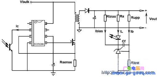
**Figure 3: TL431 in Shunt Regulator Configuration**
Assuming no Rbias, the voltage divider formed by Rupp and Rlow must supply a current greater than the TL431’s reference pin bias current (up to 6.5 mA). For a 12V output, if the bridge current is 1 mA, then Rlow = 2.5kΩ and Rupp = 9.5kΩ. A smaller bias current can be used to reduce standby power under no-load conditions.
Once the bridge current is set, RS is calculated to ensure the optocoupler collector or feedback pin stays below 1.2V during no-load operation. In the NCP1200, an 8kΩ pull-up resistor is connected between pin 2 and the internal 5V reference. If the feedback current is 475 μA, the voltage at pin 2 is 5 - (475 μA × 8kΩ) = 1.2V. Considering a 50% CTR, RS should be less than 8.94kΩ, so 8.2kΩ is chosen.
If the CTR is poor (e.g., 150%), the LED current required is small. With an 8.2kΩ resistor, the bias current changes with load and CTR. To ensure proper operation, a bias resistor Rbias is added to provide a stable current. Calculating for the worst-case scenario (heavy load and high CTR), the cathode voltage is 9.64V, and Rbias = 2.36kΩ (or 2.2kΩ for standard values).
With Rbias in place, the total bias current increases, ensuring the TL431 operates within safe limits. Experiments on an NCP1200-based power supply showed that adding a 3.3kΩ bias resistor reduced the output impedance from 57mΩ to 4mΩ.
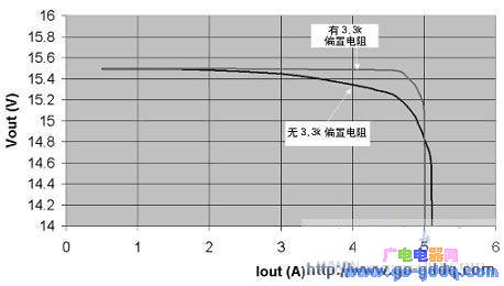
**Figure 4: Impact of Bias Current on TL431 Performance**
In conclusion, properly biasing the TL431 with an external resistor is essential for optimal performance. If minimizing no-load standby power is a priority, alternatives like the TLV431 (Vref = 1.24V) or NCP100 (Vref = 0.7V) offer lower bias current requirements. Additionally, the series resistor RS should be carefully selected to match the optocoupler’s characteristics and ensure sufficient DC gain.
Solar Energy System
A solar energy system is a complete setup that harnesses solar energy to produce electricity and may include solar panels, inverters, batteries, and the necessary wiring and mounting equipment. A solar power system is a complete setup designed to harness solar energy and convert it into usable electricity. The core components typically include solar panels, inverters, energy storage batteries, and various mounting and monitoring systems. This solar system design can be used in residential, commercial, or utility-scale applications to generate clean, renewable energy.
key components
1. Photovoltaic (PV) Panels: These are the primary components that convert sunlight into electricity. They are made up of photovoltaic cells, which are typically made from silicon or other semiconductor materials.
2. Inverter: This component converts the direct current (DC) electricity generated by the PV panels into alternating current (AC), which is the type of electricity used in homes and businesses.
3. Battery Storage: Optional but increasingly common, battery storage allows homeowners to store excess electricity generated during daylight hours for use when the sun isn't shining, providing energy independence and reducing reliance on the grid.
4. Monitoring System: This allows homeowners to track the performance of their solar system, showing how much electricity is being produced and how it is being used.
5. Mounting Structure: Panels need to be securely mounted on rooftops or other locations to ensure they receive maximum sunlight throughout the day.
6. Electrical Connections: Wiring connects all the components together and to the electrical grid, allowing the system to feed power back into the grid when production exceeds consumption.
Advantages of a solar energy system include reduced electricity bills, environmental benefits due to lower carbon emissions, potential government incentives or rebates, and increased property value.
Solar System Design,Solar Power System,Solar Electric System,Solar Powered Systems
Ningbo Taiye Technology Co., Ltd. , https://www.tysolarpower.com