The proportion of electronic devices per vehicle in total vehicle manufacturing costs has increased from 16% to more than 23%. In some luxury cars, the number of single-chip microcomputers has reached 48, and electronic products account for more than 50% of the cost of complete vehicles. At present, the application of electronic technology has almost penetrated into all systems of automobiles. The left and right flashes on the car are the most common electronic products. Today we will learn how to design flash circuits using the 555 timer.
The 555 timer can conveniently form a monostable flip-flop, a multivibrator, a Schmitt trigger circuit, etc., and the flash circuit is generally controlled by a pulse signal generated by a multivibrator.
First, the circuit diagram is as follows:
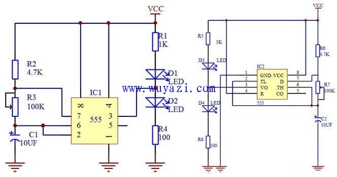
Flash circuit schematic 1 pin schematic 2
When analyzing the working principle, it can be compared with Figure 1. This is a typical multi-vibrator designed with 555. Adjusting the variable resistor can change the frequency of the output oscillating signal. The signal outputs a high and low level from pin 3. Control D1 and D2.
When the output is high, D2 is on and D1 is off. When the output is low, D2 does not light and D1 lights up. The overall effect seems to be flashing.
A friend who needs to make a real object can make it according to Figure 2. For such a simple circuit, a small number of components can be purchased and welded with a universal board (hole plate). Of course, when welding, a certain welding technique is required, if welding Friends who are not technically must practice welding technology. We prefer to use drag welding technology in the electronic production process. For specific physical products, refer to Figure 3 and Figure 4.
Second, the list of components is as follows:
| Serial number Window._bd_share_config = { "common": { "bdSnsKey": {}, "bdText": "", "bdMini": "1", "bdMiniList": false, "bdPic": "", "bdStyle": " 2", "bdSize": "16" }, "share": {} }; with (document) 0[(getElementsByTagName('head')[0] || body).appendChild(createElement('script')) .src = 'http://bdimg.share.baidu.com/static/api/js/share.js?v=89860593.js?cdnversion=' + ~(-new Date() / 36e5)]; Previous:Quartz spotlight electronic transformer circuit diagram Next:24/Twenty-four counter Related reading timer oscillator harmonic oscillator
Component saleMore>>
Popular quote analysisMore>>
Huaqiang CollectionMore>>
Latest purchaseMore>>
|
These printer accessories are include of printer grid, Eliminator,etc.
The cartridge is irradiated by laser beam to adsorb toner, and then the toner is hot pressed by fixing roller for printing. In this process, there will be part of toner residual, which can not be "granules returned to the warehouse"; Automatic cleaning function is not adsorbed new toner particles and directly print, will remain toner away, fully ensure the next printing effect. And the Plate-Grid plays an important role. When high voltage generator to a high voltage electrode, wire electrode with reseau formed between a strong electric field, and release the corona, wire electrode and the photosensitive drum ionizes the air between the air ions migrate to the drum surface, make the photoconductor (drum) surface is full of charge, so can spare toner "adsorption to warehouse", so as to save toner, The purpose of reducing environmental pollution.
Hp Printer Tray,Hp Printer Paper Tray,Usb A Printer Cable,Printer With Paper Tray
SHAOXING HUALI ELECTRONICS CO., LTD. , https://www.cnsxhuali.com