With the rapid development of information technology, network communication is becoming more and more important, and Ethernet has become the main medium for the interconnection of various control system interfaces. In special applications such as financial institutions and military applications, the stability of the network system is very high. In order to improve the reliability and invulnerability of the system, a dual-redundancy design method is adopted. The implementation of the dual redundant network is based on fault detection, through software inspection, switch and network card network node collaborative processing. The construction method of the redundant network is usually to use dual network cards in each network node, connected by two HUBs or switches in the middle. In this way, when a network card, network cable or HUB of a certain node fails, the system will enable another redundant network card so that the system can still operate normally. This paper proposes two redundant network construction schemes based on BF537.
1 Structural characteristics of BF537
BF537 is an upgraded product of the Blackfin family. It has a rich interface based on the standard Blackfin core, and an Ethernet MAC controller is integrated inside. The Blackfin core contains 2 multiplier / accumulators (MAC), 2 40-bit ALUs, 4 dedicated 8-bit ALUs for video, and 1 40-bit shifter. The arithmetic unit processes 8, 16, or 32-bit data from the register bank. Each MAC can complete a 16-bit × 16-bit multiplication operation per cycle, and accumulate the result into a 40-bit accumulator to provide 8-bit precision expansion. The ALU unit performs standard arithmetic and logical operations. Because the two ALUs have the ability to operate on 16 or 32-bit data, the flexibility of the arithmetic unit can meet the requirements of signal processing in various applications. Each 32-bit input register can be used as two 16-bit registers, so each ALU can complete a very flexible single 16-bit arithmetic operation. By using the register as two 16-bit operands, double 16-bit or single 32-bit operations can be completed in one cycle. Better use of the second ALU, four 16-bit operations can be simply completed, speeding up the throughput of each cycle. The powerful 40-bit shifter is rich in functions, and can perform operations such as shifting, cyclic shifting, normalizing, extracting and storing data. The data used by the arithmetic unit comes from a register set with 16 16-bit operands or 8 32-bit operands.
At the same time, BF537 regards memory as a unified 4 GB address space, uses 32-bit addresses and uses a hierarchical memory structure. Level 1 (L1) memory generally runs at full speed with no or little delay. Level 2 (L2) / Level 3 (L3) are distributed on-chip or off-chip, and access to it will consume multiple processor cycles. At the L1 level, the instruction memory stores only instructions, two data memories store data, and a dedicated temporary data memory stores stack and local variable information. Instructions and data can be stored at the L2 / L3 level.
2 Dual redundant Ethernet construction scheme
The Ethernet interface circuit is mainly composed of two parts: the MAC controller and the physical layer interface (PHY). Here, two different schemes for constructing dual-redundant Ethernet are proposed based on whether an independent MAC controller is provided.
2.1 Design scheme based on independent MAC controller (Scheme 1)
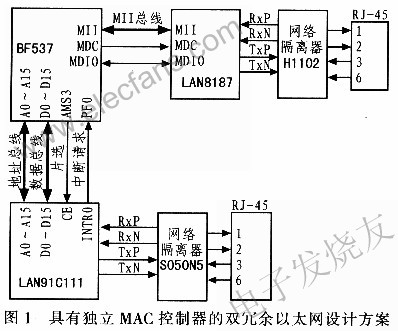
BF537 integrates a MAC controller that supports the IEEE802.3 MAC control layer protocol. It only needs to connect an Ethernet interface device externally to form a complete Ethernet channel. So choose LAN8187 of SMSC company, it has offered the standard MII bus interface, connect with BF537 conveniently, the connection way is shown as in Fig. 1. Send and receive data on the MII bus, MDC and MDIO are used to complete the reading and writing of the interface chip LAN8187 register. Hereinafter referred to as the main network channel, the Ethernet channel formed by the BF537 MAC controller and the physical layer interface chip LAN8187.
If a dual-redundant network channel is required to have an independent MAC controller, an Ethernet controller needs to be extended outside the BF537. As shown in Figure 1, the LAN91C111 from SMSC is also selected and connected to it through the BF537's external bus. Select the LAN91C111 16-bit bus working mode to connect A0 ~ A15 to the BF537 address bus, D0 ~ D15 to the BF537 data bus, and the chip selection of LAN9lClll is controlled by the BF537 AMS signal, and the external PF pin responds from LAN91C111 Interrupt request.
2.2 Design scheme based on shared MAC controller (Scheme 2)
From an application perspective, even if the system has an independent MAC controller, in practice, two MAC controllers are required to have the same physical address, because if the MAC addresses are different, redundant switching will cause the ARP binding table in the protocol layer. Changes, remapping the relationship between the physical address and IP address in the ARP table will increase the time for redundant switching, affecting the real-time nature of network communications.
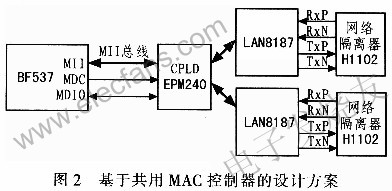
Therefore, a design scheme of a MAC controller and two Ethernet interface chips is proposed. The design scheme transfers the BF537 MII bus to two IAN8187 through one CPLD, and the timing of the transfer is controlled by BF537. In this way, two Ethernet communication channels are formed, which greatly simplifies the design and improves the real-time nature of redundant switching. The design scheme is shown in Figure 2.
3 Redundant switching software design
3.1 Network status monitoring
The realization of redundant switching first lies in real-time online monitoring of the network. The detection method is based on the LAN8187 register. Table 1 defines the IAN8187 register.
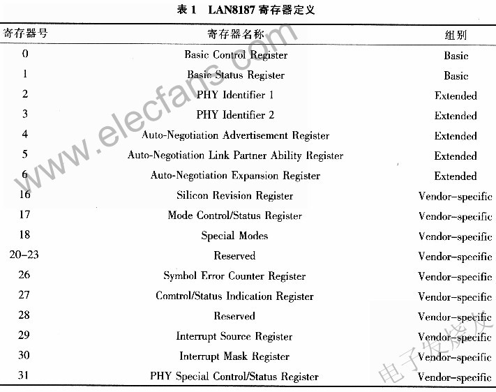
In Table 1, Basic Control Register is the basic control register. By configuring its bits, it completes the functions of chip soft reset, 10 M / 100 M selection, full-duplex / half-duplex selection, LookBack mode selection, and auto-negotiation. Basic Status Register is the basic status register, and the basic status of the network such as auto-negotiation results and network physical connection status can be obtained by querying it. The PHY IdenTIfierl / PHYIdenTIfier 2 register identifies the Chip ID of the chip. Therefore, real-time monitoring of the network status is actually reading the Basic Status Register in real time and making judgments on the results.
3.2 Programming
You can complete the reading and writing of the LAN8187 register by operating the register EMAC_STAADD of BF537. The functions for reading and writing the LAN8187 register are defined as:
u16 RdPHYReg (u16 PHYAddr, u16 RegAddr);
void WrPHYReg (u16 PHYAddr, u16 RegAddr, u32 Data);
Among them PHYAddr is the physical address of the chip, RegAddr is the register address.
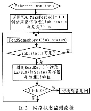
The monitoring of the Basic Status Register uses a polling mechanism, which sets a semaphore Link_status, whose period is 2 ms, so the Ether moniter thread is triggered every 2 ms. By calling RdPHYReg () function in Ether_moniter, the value of Basic Status Register is read, and the Link bit is judged. The Ether_moniter thread flow is shown in Figure 3.
For design option 1, when it is detected that network switching is required, the current network card needs to be disabled to initialize the standby network LAN91C111 and set the same IP address and MAC address. For scenario 2, you only need to inform CPLD to switch the channel to the standby LAN8187 interface.
4 Redundancy switching test
A simple host computer test program developed with Visual C ++ 6.0 sends a UDP datagram every 1ms and writes a different serial number for each datagram. Write a program in BF537 to continuously receive the datagram from the host computer, and then create a network communication failure, the redundant network constructed in this article will automatically switch to the standby channel to continue to receive the datagram from the host computer, and finally detect the received datagram The serial number determines the time it takes to switch redundantly. Test the switching of the redundant network constructed by the two schemes respectively, and the results are shown in Table 2.
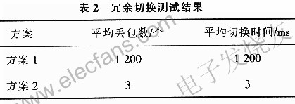
From the experimental results, it can be seen that scheme 2 has the advantages of fast switching and low packet loss rate; the average packet loss number of scheme 1 is much greater than that of scheme 2, and the switching time is long.
5 Conclusion
This paper presents two schemes for building dual redundant Ethernet based on BF537, and discusses its principle, device selection, connection method, and software design. Finally, after testing, the switching effect and time of scheme 2 are very ideal, and it is finally applied in the actual project.
| About Film Overcoated With F46 Copper Flat Wire |
Polyimide-F46 combined film wrapped sintered copper flat Magnet Wire insulation wire
This product provides high heat resistance, high cut through, solvent resistance, radiation resistance, cold resistance, freon resistance , etc .
The technical indexes for aluminium core enameled wire comply with enterprise standards extablished in reference to national standards .

Inner packing: in different wooden bobbin ,
Outer packing:wooden pallet with steel strip or according customers' special requirements
Film Overcoated With F46 Copper Flat Wire
Film Wrapped Copper Wire,Film Overcoated With F46 Copper Flat Wire,F46 Copper Flat Wire,Film Covered With F46 Copper Flat Wire
HENAN HUAYANG ELECTRICAL TECHNOLOGY GROUP CO.,LTD , https://www.huaonwire.com