With the increasing attention of green lighting and smart homes, short-range wireless communication technologies are gradually being applied in related fields. To this end, this paper designed and completed a wireless LED lighting system based on TI CC430 series and UCC28810, aiming to provide a novel, efficient and intelligent wireless LED lighting system solution.
1. Introduction to wireless LED lighting system
The lighting system is closely related to people's lives, but most of the lighting systems currently use various types of ordinary switches to turn on and off the lamps. The brightness adjustment of the lights is also adjusted by ordinary dimming and opening. Every time the operation of the lighting system has to go to the switch to complete, and a switch generally only corresponds to one luminaire, resulting in the need to install a lot of switches, so it is very necessary to design a wireless remote control transmitting and receiving device that integrates dimming and switching. Improve the intelligence of the lighting system. This will effectively overcome the drawbacks of traditional wired control, reduce the layout of the circuit, and allow people to operate the lighting system freely anywhere. Based on this demand, this paper designs a solution for wireless LED lighting system with very rich functions. Specifically, there are several functions:
1. The function of centralized control and multi-point operation;
2, soft start function: When the light is turned on, the light is gradually brightened by the dark, when the light is turned off, the light is dimmed from light. Avoid large current surges, protect the lighting system and extend the service life;
3, light and dark adjustment function: adjust the brightness of different lights, easy to operate;
4. Fully open and full memory and memory function;
5, timing control function;
6, brightness adaptive adjustment;
2. System structure and overall design
This paper is designed using TI's CC430 wireless communication platform, which combines a 16Bit-based ultra-low-power MSP430 core with an industry-leading CC1101 RF transceiver of less than 1GHz. The perfect combination enables a unique low power/high performance combination with unprecedented levels of integration, resulting in more advanced selectivity and high blocking performance, ensuring reliable communication even in noisy environments. It can take advantage of its peak performance of up to 25MHz and consume only 160uA/MHz. For CC430-based devices, TI offers a broad portfolio of MSP430 MCU peripherals, such as 12-Bit ADCs, LCD drivers, and high-performance digital and analog peripherals such as comparators. In addition, the AES-128 hardware security module ensures communication security.
The overall block diagram of the wireless LED lighting system is shown in Figure 1. The control section is designed to be powered by a dual AA battery.
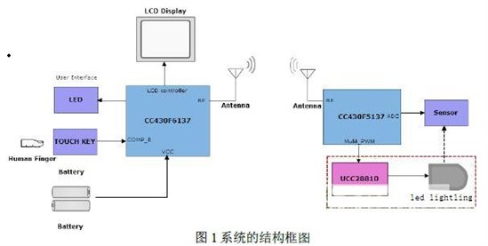
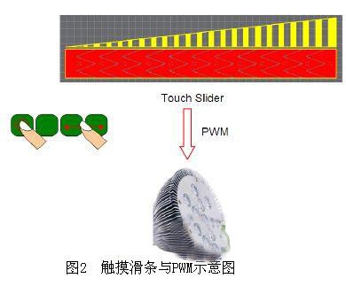
Handheld remote control module based on CC430F6137 with segment LCD driver, rich I/O port resources and comparator capable of building touch function; and receiving end based on CC430F5137 with 12-Bit ADC and many more The PWM module of the channel. By constructing the touch slider and button function on the comparator B of the control terminal CC430F6137, the touch position of the slider is detected and converted into the duty ratio of the PWM, and the corresponding modulation parameters are transmitted/received through the bilateral RF module, and then The receiving end CC430F5137 generates a PWM signal that adjusts the brightness of the LED lamp, and modulates the driver module UCC28810, as shown in Figure 2.
3. Hardware circuit design
3.1 RF module hardware circuit design
The CC430's RF module uses the industry-leading CC1101 RF transceiver of less than 1 GHz. This part is based on direct synthesis of RF frequency. The RF synthesizer includes a complete chip LC-VCO and a docking mode mixer for frequency. synthesis. The receiving unit of the radio frequency preamplifies the RF signal through a low noise amplifier (LNA), and then performs filtering, data demodulation, and synchronization packets on the intermediate frequency signal. The frequency range supported by CC430 is: 300MHz~348MHz; 389MHz~464MHz; 779MHz~928MHz; in this design, the carrier frequency of 433MHz is used. In view of the lower transmission rate required by the application, 3.2Kbps is selected; The output power is adjusted by PATABLE to meet different distance requirements.
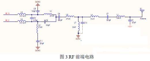
The hardware circuitry of the RF module is especially important throughout the system design, as shown in Figure 3. C5, C9, L3 and L8 in the figure form a balanced converter to convert the differential port RF_N/RF_P balancing circuit on the CC430 into a single-ended unbalanced RF signal, which facilitates the flow of the vibrator outside the cable shield. The frequency current is cut off. L5, C10 and L4 in the figure form a bandpass filter; L2, L6 and C8 form a lowpass filter. In this design, the antenna of the RF uses a whip antenna or a ceramic antenna.
3.2 Hardware circuit construction of touch slider
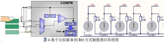
In this design, the control end portion is a handheld remote control module. The human-computer interaction interface designed is mainly LCD display and touch buttons. Among them, the function of touching the slider is used to adjust the brightness of the LED, which is one of the more vivid and novel designs in the system. It makes full use of MSP430's own resource characteristics. On the CC430F6137 integrated comparator COM_B and PCBLayout sensing capacitor, it constructs a touch-button function based on relaxation mode (RO), since it has its own REF reference voltage in COMP_B. The network is configured so there is no need to implement the reference voltage network using external hardware like COMP_A. The principle is shown in Figure 4. The TIerA measures the number of oscillations of the RC oscillator circuit in a fixed time. When the human touches the sensing capacitor, it changes its own capacitance value, so that the corresponding number of oscillations changes significantly. To determine the state of touch/non-touch. Build a 4/5 touch slider with 2 touch buttons.
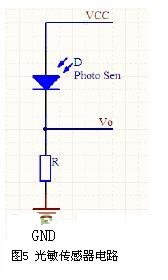
3.3 sensor hardware circuit design
The use of a light-sensitive sensor enables the LED lighting system to achieve brightness self-adjustment. The hardware circuit is shown in Figure 5. Photosensitive sensors use photoresistors, which have good optoelectronic characteristics and price advantages, and are very suitable for use in light intensity detection applications. In the system, the detection of the Vo voltage is mainly reflected, and the change of the light intensity is reflected, and then the PWM is modulated accordingly.
Micro LED light wrapped by clear PVC wire for tangle free, It is easy to pack then the normal one without PVC wire. After adding PVC line, the light color is more transparent and clear. The LED color can be white, warm white, etc.We can make the light in curtain, waterfall, net design. The copper wire won't be etangled. The net light can be used in the big shopping mall for decoration. simple decoration and special design. daily & festival light for indoor & outdoor decoration. Operating by low voltage for safety and convenient use.
Tangle Free Item Lights
Free Item Lights,LED Garden Solar Light,Solar Lawn Light,LED Solar Garden Light
Heshan Jianhao Lighting Industrial Co., Ltd. , https://www.sunclubtw.com