In recent years, with the improvement of automation technology and people's living standards, the concept of smart home has been accepted by more and more people. The so-called smart home is based on the residential platform, using integrated wiring technology, network communication technology, security technology, automatic control technology, audio and video technology to integrate home life related facilities, and build an efficient management system for residential facilities and family schedules. Improve home safety, convenience, comfort, and artistry, and achieve an environmentally friendly and energy-saving living environment. In the smart home system, the intelligent water leakage prevention system plays an important role in home safety. Usually due to temporary negligence, such as forgetting to turn off the faucet when the water is stopped, the water is not smooth, the pipeline is damaged, and other accidents cause the home to leak water. In many cases, the situation is serious, not only the loss of the home, but also the same building. In this paper, a home intelligent waterproof system is designed, which can automatically detect the accidental water leakage in the selected area, cut off the water pipe in time through the electromagnetic valve, and accompany the sound and light alarm to indicate the flooding event, reduce the deterioration of the water leakage condition, and effectively prevent each The losses are further expanded.
1 System design The home intelligent waterproof system is mainly divided into four parts, including the detection component, the MCU control part, the alarm and button circuit, the solenoid valve and the drive circuit. The state of the water sensor is detected by the parallel port I/O of the MCU, and the LED display circuit and the buzzer alarm circuit are controlled, and the water circuit of the water solenoid valve is controlled by the driving circuit. The system block diagram is shown in FIG. 1 .
This article refers to the address: http://

The system continuously monitors the state of the water sensor through the MCU. If a leak is found, the LED display and the buzzer alarm are issued, and the delay is delayed for a period of time, and then the solenoid valve is activated to close the water pipe. If someone in the house checks the water leak after hearing the alarm, you can manually cut off the water pipe or turn off the alarm system (if it is found to be a false alarm).
2 hardware design
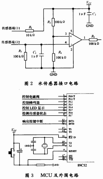
2.1 Water sensor detection circuit The circuit adopts an appropriate electrode type water sensor, which is arranged in the area to be monitored, and can be a fixed area or multiple areas for simultaneous monitoring. The state of the sensor is determined by voltage detection mainly according to the principle of variation of the electrode immersion resistance. The external state level is obtained by the voltage comparator and sent to the MCU unit for detection processing. The water sensor interface circuit is shown in Figure 2.
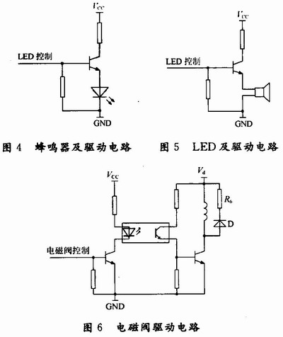
2.2 MCU control circuit MCU unit circuit mainly completes the functions of monitoring, judgment, alarm control and human-computer interaction control of the whole system. In this scheme, Atmel's 89C52 single-chip microcomputer is selected as the control MCU. Its structure is simple, the price is low, the versatility is good, and the internal functions such as CPU, RAM, ROM, timer/counter and multi-function I/0, serial communication, etc. are integrated. The component has flexible programming to control the external I/O interface. In combination with this case, the state of the water sensor is detected by the parallel I/O of the MCU, and the LED display circuit and the buzzer alarm circuit are controlled, and the on/off of the water solenoid valve is controlled by the drive circuit. MCU and peripheral circuits are shown in Figure 3.
2.3 Display and alarm circuit The buzzer selects the active buzzer, which integrates the multi-vibrator inside. It only needs to apply the necessary DC level externally, and its driving and control circuit is simple. At the same time, the LED is driven to illuminate the diode when a leak is detected. The buzzer and drive circuit are shown in Figure 4. The LED and drive circuit are shown in Figure 5.
2.4 Solenoid valve drive circuit Solenoid valve is an automatic basic component used to control the direction of the fluid. It is usually used for mechanical control and industrial valves to control the direction of the medium to control the valve switch. In this scheme, the water pipe is unobstructed under normal conditions, so the normally open solenoid valve is selected, and the pilot valve receives the electric control signal switch to drive the main valve to operate, cutting off the water pipe, thereby avoiding further deterioration of the water leakage condition. Since the output control signal of the single chip is TTL level, the solenoid valve cannot be directly controlled, and the drive circuit needs to be added, as shown in FIG.
The circuit shown in Fig. 6 uses a photocoupler to isolate the control signal output circuit from the solenoid valve drive circuit, thereby suppressing high-frequency interference of the drive circuit from entering the control circuit portion to ensure normal operation. Resistor R6 and diode D form a discharge path when the injector is turned off to prevent damage to the power transistors, and they form a crowbar circuit with the solenoid coil.
3 software design
3.1 System Software Flow When the system control software uses cyclic scanning, the water sensor status is monitored in real time. If a sensor abnormality is detected, the audible and visual alarm circuit is activated. If there is someone around, to confirm whether there is water leakage, you can manually close the inlet valve; if there is no one around, the system will start the solenoid valve control circuit within 5s after the alarm, automatically cut off the inlet valve and wait for the personnel to solve the problem. The software flow chart of the single chip microcomputer is shown in Figure 7.

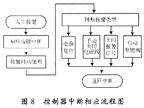
3.2 Interrupt subprogram design In the system, the button behavior of human-computer interaction is taken as an interrupt, and its priority is relatively high. In any process of system operation, priority can be given to manual commands. The key interrupt types are divided into circuit reset, manual closing of the solenoid valve, manual opening of the solenoid valve, and closing of the alarm. The process of the broken subroutine is shown in Figure 8.
4 Conclusion In view of the leakage prevention problem in key areas of smart home, a scheme based on water sensor detection and MCU control is proposed. When a water leakage condition is detected, the control start solenoid valve automatically closes the water pipe and alarms by sound and light. At the same time, the human interaction capability is increased, and manual instructions are prioritized. After testing and trial use, the program is economical and reliable, and it can effectively handle the water leakage problem in the home. At the same time, it can be extended to the computer room, file management room, warehouse and other places that need strict waterproofing, and has a very broad prospect. In the future work, you can consider to further increase the system function, such as adding GPRS information communication function, you can access the communication network to realize remote transmission of alarm information, etc.; you can also access the property service network through power line communication to achieve remote Monitoring and control, etc.
Uvc Light,T5 Uvc Lamp,T5 Uvc Tube,T5 Uvc Bulb
Changxing leboom lighting product CO.Ltd. , http://www.leboomuv.com