Headphone amplifier requirements
This article refers to the address: http://
--- Headphone amplifiers are mainly used in portable audio devices. Like other portable electronic products, they require low operating voltage, low power consumption, and small package size. Headphone amplifiers also have their own technical parameters, requiring total harmonic distortion plus noise (THD+N), high power supply rejection ratio (PSSR), high signal-to-noise ratio (SNR), and high efficiency. Different amplifiers have different additional features, such as built-in digital volume control, built-in DAC, and more. The specific performance indicators are as follows.
â— Output power POUT
--- Headphone amplifier output power is small, generally 20 ~ 100mW (actual output power is related to the working voltage, and related to the load resistance and THD + N size). The load resistance of a stereo earphone is generally 16 Ω or 32 Ω, and the output power of the load resistance is small.
â— THD+N
The index of ---THD+N is generally in the range of 0.01% to 0.2%, and the Hi-Fi level is less than 0.01%. This index is related to the magnitude of the load resistor RL and the output power POUT. If the RL is different and the POUT is different, the index is quite different. For example, for the same headphone amplifier, THD+N=0.006% when RL=32Ω, POUT=12mW, f=1kHz, and THD+N=0.015% when RL=16Ω, POUT=15mW, and f=1kHz. Therefore, when comparing the THD+N indicators of different headphone amplifiers, it must be comparable when the basic conditions are similar.
â— SNR
--- SNR is generally in the range of 60 ~ 90dB, its size is related to POUT, some products have SNR of about 100dB.
â— PSRR
--- PSRR high headphone amplifier, its performance is less affected by power supply voltage fluctuations (PSRR high amplifier can be powered without a regulated power supply). The PSRR is generally 60 to 80 dB, and the performance is as good as 90 dB.
Reduce the working voltage
--- In order to reduce the size and weight of portable products, the most effective way is to use lithium ion batteries with high energy density and small volume, but lithium ion batteries are expensive. With 1-2 alkaline or rechargeable batteries, the cost of manufacturing and use is much reduced. In recent years, some manufacturers have developed a headphone amplifier (1 section 5# or 7# alkaline battery or Ni-MH, Ni-Cd battery) powered by only one battery, which is more popular among consumers, and its working voltage is 0.9V~1.8V. It can be powered by one alkaline battery or one rechargeable battery, which greatly reduces the cost of some low-end MP3 players, and the sales volume increases greatly.
---Because it is a single power supply, the voltage amplitude of the headphone amplifier output is affected by the operating voltage. Although an output-rail-to-rail amplifier can be used, the output of the 1V operating voltage is always less than 1V.
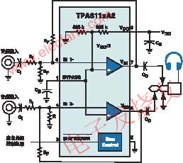
--- In order to reduce the operating voltage, and to ensure a large enough output voltage amplitude, a voltage reversed charge pump circuit is integrated in the headphone amplifier to convert the input VDD to -VDD, and the headphone amplifier is powered by a single power supply. Turned into positive and negative power supply, the output voltage amplitude has doubled, as shown in Figure 1.
Measures to reduce external components
--- The typical application circuit of Texas Instruments' TPA611xA2 headphone amplifier is shown in Figure 2. Two 325kΩ resistors inside the amplifier form a voltage divider that provides two channels of op amp bias voltage (1/2VDD) and a shutdown control (SHUTDOWN) terminal (active low) to turn off the amplifier and consume power Less than 10μA.
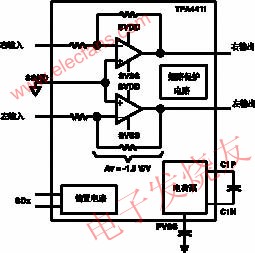
---Reducing peripheral components not only saves printed circuit board area, but also improves performance. Figure 3 shows the internal structure and peripheral components of the headphone amplifier TPA4411 introduced by Texas Instruments in August 2004. The TPA4411 uses a fixed gain (AV=-1.5V/V), eliminates the need for an output DC blocking capacitor, simplifies peripheral components, and has the following advantages: reduced PCB area; reduced component cost; improved THD+N performance; no need to consider output capacitors The effect on low frequency response. Compared with Figure 3, Figure 2 reduces the four gain setting resistors and eliminates two output capacitors.
--- In order to solve the amplifier's gain requirements of different audio devices, Maxim Corporation (MAXIM) introduced the headphone amplifier MAX9725 in November 2004, with different gains for users to choose. The MAX9725A, MAX9725B, MAX9725C and MAX9725D have gains of -2V. /V, -1.5V/V, -1V/V and -4V/V. It can also be seen from Figure 1 that the new headphone amplifier reduces the external components.
Add additional features
--- Good performance of the headphone amplifier generally has shutdown control, overheat protection and short circuit protection, suppression of power on/off noise (click and pop), and noise suppression. The new headphone amplifier also adds additional features such as digital volume control (with I2C interface and digital volume circuitry), built-in DAC, left and right channel line outputs, and more.
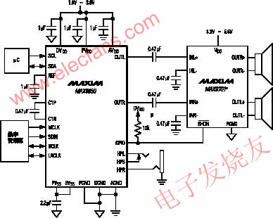
---MAX9850 is a headphone amplifier with DAC introduced by Maxim in November 2004, and has stereo line output. The device operates from a single supply of 1.8 to 3.6V; it can output 30mW at 1.8V supply; no output capacitor is required; PSRR is 91dB at 1kHz; clock frequency is up to 40MHz; flexible I2S compatible digital audio interface; I2C headphone volume and quiet Noise control; stereo line input and output; no click and pop; two-wire (I2C) compatible control interface; 28-pin QFN package. The device is mainly used in MP3 players, portable multimedia players, mobile phones, smart phones, portable DVDs and so on.
--- The typical application circuit of the MAX9850 is shown in Figure 4. In Figure 4, stereo headphones can be plugged into HPL, HPS, HPR headphone jacks. In addition, a 0.47μF input capacitor is output from the OUTL and OUTR lines, and is input to the MAX9701 power amplifier to drive the left and right speakers.
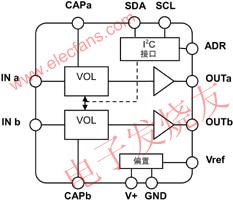
--- NJW1109 from Japan JRC is a headphone amplifier with electronic volume control. Figure 5 is the internal block diagram of the device. The microprocessor controls the volume via SDA and SCL. The device has a built-in 1/2V+ bias circuit (Bias) with an external 10μF bypass capacitor at the Vref terminal. INa and INb are audio signal inputs, and OUTa and OUTb are two outputs (connected to stereo headphones). SDA is the I2C bus data input, SCL is the I2C bus clock input, and ADR is the I2C bus slave address select. The device is available in a 14-pin DIP package, DMP package and SSOP package.
Class D high efficiency amplifier
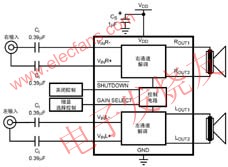
--- Class D switching audio amplifiers are highly efficient and are typically used in power amplifiers with output powers of several watts or tens of watts. In order to extend battery life and reduce power consumption, such amplifiers are also used in new mobile phones, PDAs, and portable audio devices. For example, the National Semiconductor Corporation introduced the LM4666 in May 2004 as a high-efficiency stereo 1.2W switching audio amplifier with a typical operating voltage of 79V at a working voltage of 3V, a load resistor of RL=8Ω, and an output power of POUT=100mW. %. A typical application circuit is shown in Figure 6.
--- Features of the device include: no output filter; 6dB or 12dB gain; few external components; "å’”", "popping" suppression circuit; micro power shutdown control; short circuit protection; small Size 14-pin SDA package. Gain selection (GAIN SELECT) is 6dB for the high level and 12dB for the low level. Shutdown when SHUTDOWN is tied low.
Fiber Optical Distribution Box(Metal) Fiber Optic Distribution Box is specially designed for FTTH or FTTB for Indoor/Outdoor application. It is can manage single,ribbon & bundle fiber cables. It consists of splicing, distribution and panel with ensures the excess fiber cords and pigtails in good order, no interval and easy for management and operation. It offers mufti-functions of distribution management.
Indoor Fiber Optical Distribution Box(Metal)
Indoor Fiber Optical Distribution Box(Metal),Fiber Optic Distribution Cabinet,Metal Electrical Boxes,Metal Equipment Cabinet
Sijee Optical Communication Technology Co.,Ltd , http://www.sijee-optical.com