The biggest challenge for developers is the lack of clear separation between core and non-core domains. As a result, most of their time is spent writing code that isn't reusable or relevant to the product's competitive advantage. This often leads to neglecting critical areas like requirements, algorithms, user experience, and software engineering practices. Consequently, the amount of code maintenance becomes significantly higher than the initial development investment.
Teams that create great products not only have stable teams but also enjoy better income and a different mindset. They use the right development strategies and methods, mastering technologies quickly and effectively. While many companies have high-paying employees, the difference lies in how these teams leverage their skills to build valuable, marketable products. Others' products are sold successfully, while yours may not even be viable. This waste of resources can cost more than just money—it can cost opportunities for future value creation.
More than a decade ago, the author faced similar challenges and decided to focus on developing standardized platform technology for both software and hardware. This led to the creation of AWorks. Ametal, derived from the AWorks-Nano subset, not only enables cross-platform compatibility but also defines standard interfaces for peripheral devices, making it possible to deliver "on-demand" services to users. This vision has now become a reality.
ZLG provides a wide range of standard peripheral drivers and protocol components, aiming to build a complete ecosystem. Whether you choose any MCU, as long as it supports Ametal, you can achieve "one-time programming, lifelong use." This means you won’t have to reinvent the wheel every time.
**6.1 E2PROM Memory**
E2PROM (Electrically Erasable Programmable Read-Only Memory) is a type of memory that retains data even after power is turned off. This section uses FM24C02 as an example to explain how to use similar non-volatile memory in Ametal.
> > >
**6.1.1 Device Introduction**
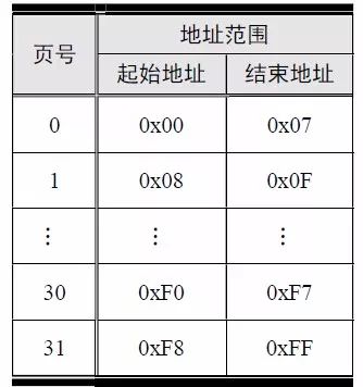
The FM24C02 has a total capacity of 2K bits (256 bytes). Each byte corresponds to a unique address, so its address range is from 0x00 to 0xFF. The page size is 8 bytes, meaning that writes cannot cross page boundaries. For example, if you write at address 0x08, the next write must start at 0x10 or later. The internal structure is shown in Table 6.1.
Table 6.1: FM24C02 Memory Organization Structure
The communication interface of the FM24C02 is a standard I²C interface, requiring only two signal lines: SDA and SCL. Using the 8-pin SOIC package as an example, the pinout is shown in Figure 6.1. The WP pin is used for write protection; when it’s pulled high, all write operations are blocked. Typically, this pin is grounded for normal operation.
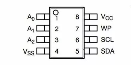
Figure 6.1: FM24C02 Pin Definition
The A2, A1, and A0 pins determine the I²C slave address of the FM24C02. Its 7-bit address is 0101 0A2A1A0. If there is only one FM24C02 on the I²C bus, A2, A1, and A0 are grounded, resulting in an address of 0x50.
In Ametal, the device address is represented as a 7-bit address, without needing to handle read/write direction bits. The MicroPort-EEPROM module connects to the AM824-Core via the MicroPort interface, as shown in Figure 6.2. The E2PROM used here is the 256-byte FM24C02C from Fudan Micro-Semiconductor.
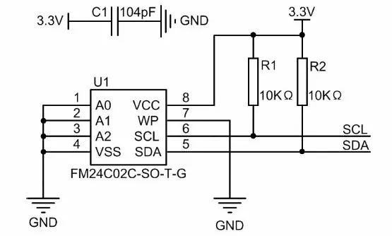
Figure 6.2: E2PROM Circuit Schematic
> > >
**6.1.2 Initialization**
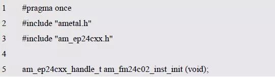
Ametal provides driver functions for various I²C interface E2PROMs, including FM24C02, FM24C04, and FM24C08. Below is an example using FM24C02. The function prototype is defined in am_ep24cxx.h:
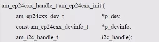
This function returns a device instance handle, fm24c02_handle. The p_dev parameter points to an instance of type am_ep24cxx_dev_t, and p_devinfo points to an instance information of type am_ep24cxx_devinfo_t.
**Instance**
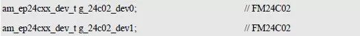
Each FM24C02 can be considered an instance of EP24Cxx. An EP24Cxx abstracts an E2PROM chip representing a series of similar types. Multiple FM24C02s are multiple instances of the same EP24Cxx. If only one FM24C02 is connected to the I²C bus, an instance of am_ep24cxx_dev_t is defined as follows:

Where g_at24c02_dev is a user-defined instance. If two FM24C02s are connected, three instances need to be defined:
Each instance is initialized, and each returns a handle. This allows different handles to be passed when using other interface functions.
**2. Instance Information**
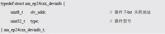
The instance information contains details about the specific device, such as its I²C slave address and model. The type am_ep24cxx_devinfo_t is defined in am_ep24cxx.h:
Supported device models have corresponding macros defined in am_ep24cxx.h. For example, the macro for FM24C02 is AM_EP24CXX_FM24C02, and the instance information is defined as:
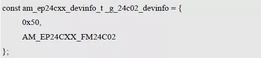
Where g_24c02_devinfo is user-defined.
**3. I²C Handle i2c_handle**
Taking I²C 1 as an example, the return value of the instance initialization function am_lpc82x_i2c1_inst_init() is passed as an argument to i2c_handle:

**4. Example Handle fm24c02_handle**
The FM24C02 initialization function am_ep24cxx_init() returns a handle of type am_ep24cxx_handle_t:

If the return value is NULL, the initialization failed. Otherwise, a valid handle is returned.
Based on modular programming principles, the definitions of the instance and instance information are stored in the configuration file, with the instance initialization function extracted through the header file. The source and header files are shown in Listings 6.1 and 6.2.
Listing 6.1: Example Initialization Function Sample Program (am_hwconf_ep24cxx.c)
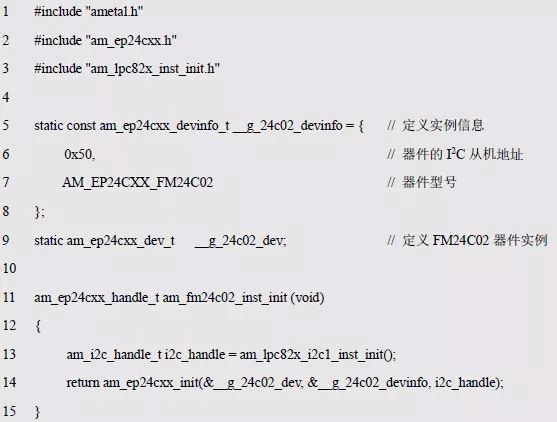
Listing 6.2: Instance Initialization Function Interface (am_hwconf_ep24cxx.h)
Afterward, the parameterless instance initialization function can be used to get the FM24C02 instance handle:

Note that i2c_handle distinguishes between I²C 0, I²C 1, etc., while the instance handle distinguishes between multiple devices connected to the same system.
> > >
**6.1.3 Read and Write Functions**
The function prototypes for reading and writing EP24Cxx series memory are shown in Table 6.2.
Table 6.2: EP24Cxx Read and Write Functions (am_ep24cxx.h)
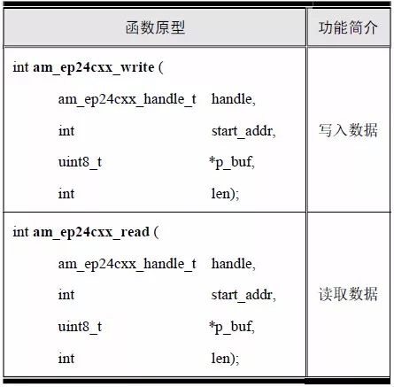
Each API returns the same meaning: AM_OK means success, negative values indicate failure, and the reason for failure can be found in the am_errno.h file. Positive values are defined by each API, though they typically do not return positive values unless specified.
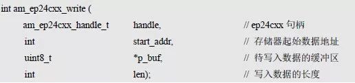
**1. Data Writing**
The function prototype for writing data starting from a specified address is:
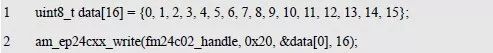
If the return value is AM_OK, the write was successful. Assume we want to write 16 consecutive bytes starting at address 0x20, as shown in Listing 6.3.
Listing 6.3: Write Data Sample Program
**2. Data Reading**
The function prototype for reading data starting from a specified address is:
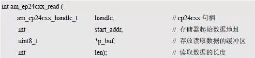
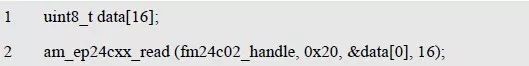
If the return value is AM_OK, the read was successful. Assume we want to read 16 consecutive bytes starting at address 0x20, as shown in Listing 6.4.
Listing 6.4: Read Data Sample Program
As shown in Listing 6.5, we can write 20 bytes of data and then read them back to compare.
Listing 6.5: FM24C02 Read and Write Sample Program
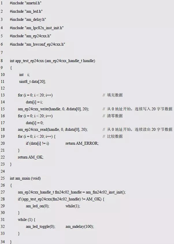
Since the app_test_ep24cxx() function takes an instance handle as a parameter, it is dependent on the EP24Cxx device and cannot be used across platforms.
> > >
**6.1.4 NVRAM Universal Interface Functions**
Since E2PROMs like FM24C02 are typical non-volatile memories, reading and writing data using the NVRAM (Non-Volatile Random Access Memory) standard interface doesn’t require handling specific devices. Before using these functions, set the AM_CFG_NVRAM_ENABLE macro in the project configuration file am_prj_config.h to 1. The related function prototypes are listed in Table 6.3.
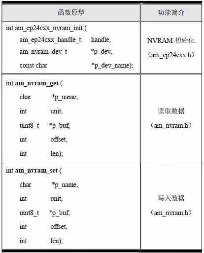
Table 6.3: NVRAM Common Interface Functions
**1. Initialization Function**
The NVRAM initialization function is used to initialize the NVRAM functionality of the FM24C02 for data reading and writing via the NVRAM standard interface. Its function prototype is:
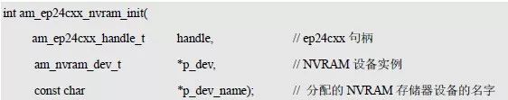
The ep24cxx instance handle fm24c02_handle is passed as an argument to the handle, p_dev is a pointer to an instance of type am_nvram_dev_t, and p_dev_name is the name assigned to the FM24C02, allowing other modules to locate the FM24C02 memory by this name.
**(1) Example (NVRAM Memory)**
NVRAM abstractly represents all non-volatile memory, and the FM24C02 can be considered a specific example of NVRAM memory. Define an instance of type am_nvram_dev_t as follows:

Where g_24c02_nvram_dev is a user-defined instance.
**(2) Instance Information**
The instance information includes only the device name specified by the p_dev_name pointer. The device is named as a string like "fm24c02". After initialization, the name uniquely identifies an FM24C02 memory device. If multiple FM24C02s exist, they can be named "fm24c02_0", "fm24c02_1", etc.
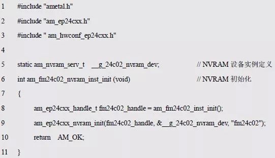
Based on modular programming principles, the code that initializes the FM24C02 to the standard NVRAM device is stored in the configuration file, and the corresponding instance initialization function is extracted through the header file. See Listings 6.6 and 6.7 for details.
Listing 6.6: NVRAM Instance Initialization Function (am_hwconf_ep24cxx.c)
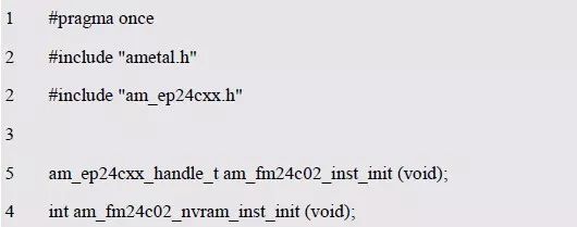
Listing 6.7: am_hwconf_ep24cxx.h File Update
Subsequently, the parameterless instance initialization function can be used to complete the NVRAM device initialization and convert the FM24C02 into an NVRAM storage device named "fm24c02":

**2. Storage Segment Definition**
NVRAM defines the concept of a bucket, and both read and write functions operate on specific buckets. NVRAM memory can be divided into single or multiple segments. The type of the storage segment am_nvram_segment_t is defined as follows:
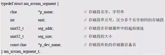
The name p_name and unit number unit uniquely identify a bucket. When names are the same, the unit number is used to distinguish between different buckets. The name of the storage segment gives each segment an actual meaning. For example, a segment named "ip" stores an IP address, and a segment named "temp_limit" stores a temperature limit value. Seg_addr is the starting address of the storage segment, and seg_size is its capacity. p_dev_name indicates the actual storage device corresponding to the bucket.
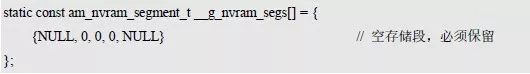
To assign a bucket to the FM24C02, set p_dev_name in the bucket to "fm24c02". Subsequent read and write operations for this segment are actually performed on the FM24C02. For management convenience, all storage segments are uniformly defined in the am_nvram_cfg.c file. By default, the storage segment is empty, as defined below:
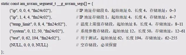
After obtaining the FM24C02 storage device, you can add some segment definitions. For example, if the application needs to store 2 IP addresses (4 bytes × 2), a temperature upper limit (4 bytes), and system parameters (50 bytes), the corresponding bucket list (array of bucket information) is defined as follows:
To make the bucket effective, the am_nvram_inst_init() function (am_nvram_cfg.h) must be called at system startup. The function prototype is:

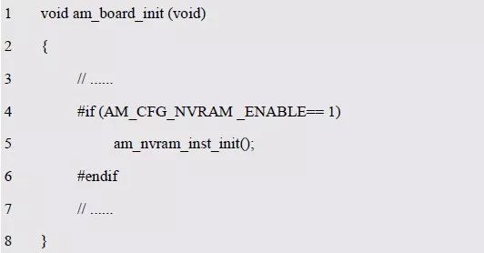
This function is usually called in the board-level initialization function and can be conditionally compiled using the AM_CFG_NVRAM_ENABLE macro in the project configuration file (am_prj_config.h), as shown in Listing 6.10.
Listing 6.8: Initializing NVRAM in Board-Level Initialization
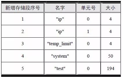
After NVRAM is initialized, based on the storage segments defined in the am_nvram_cfg.c file, a total of 5 storage segments are added. Their names, unit numbers, and sizes are listed in Table 6.4.
Table 6.4: NVRAM Buckets Defined
**3. Data Writing**
The prototype of the write data function is:

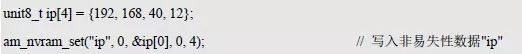
Here, p_name and unit represent the name and unit number of the storage segment, determining where the data is written. p_buf provides the data to be written to the segment, offset indicates the starting position within the segment, and len is the length of the data to be written. If the return value is AM_OK, the write was successful; otherwise, it failed. For example, saving an IP address to an IP bucket is shown in Listing 6.9.
Listing 6.9: Write Data Sample Program
**4. Data Reading**
The prototype of the read data function is:

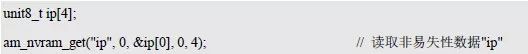
Where p_name and unit are the name and unit number of the storage segment, respectively, to determine which segment to read from. p_buf holds the data read from the segment, offset indicates the starting position within the segment, and len is the length of the data to be read. If the return value is AM_OK, the read was successful; otherwise, it failed. For example, reading an IP address from an IP bucket is shown in Listing 6.10.
Listing 6.10: Read Data Sample Program
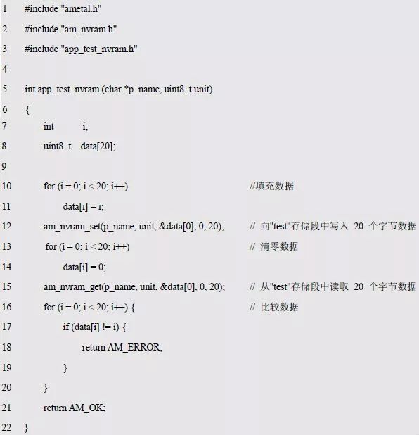
Now, a simple test program for the NVRAM general interface can be written to test whether the read and write of a certain segment is normal. Although the test program is simple, based on the modular programming idea, it's best to separate the test-related programs. The implementation and interface declarations are detailed in Listings 6.11 and 6.12.
Listing 6.11: Test Program Implementation (app_test_nvram.c)
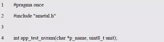
Listing 6.12: Interface Declaration (app_test_nvram.h)
The memory segment (name and unit number) to be tested is passed to the test program as parameters, and the NVRAM general interface reads and writes data to the test segment. If the read and write results match, AM_OK is returned; otherwise, AM_ERROR is returned.
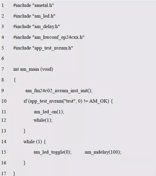
It can be seen that the application does not contain any device-specific statements. It only calls the NVRAM general interface to read and write the specified memory segment. Therefore, the application is cross-platform and can be used on any AMetal platform. Examples of interface usage and test procedures are detailed in Listing 6.13.
Listing 6.13: NVRAM Universal Interface Read and Write Sample Program
Clearly, the NVRAM universal interface improves the readability and maintainability of the program compared to the EP24Cxx read-write interface. However, calling the NVRAM common interface consumes some memory and CPU resources, especially in applications where high efficiency or limited memory is required. In such cases, the EP24Cxx read/write interface is recommended.
Chamfered Radiator,Galvanized Chamfered Radiator,Corrosion Resistant Chamfered Radiator,Power Transformer Chamfered Radiator
Shenyang Tiantong Electricity Co., Ltd. , https://www.ttradiator.com