With computer, network, mechatronics, information, and intelligent mobile robots, we can integrate the knowledge of multidisciplinary fields through mobile robot technology. The key technologies can be divided into path planning, navigation and positioning, path tracking and motion control technologies. Path planning can be divided into global and partial path planning. The global path planning is based on the overall task of the mobile robot, and the overall path task is decomposed and a global terrain database is established. The local path planning is based on the sub-task of the global planning decomposition, combined with the current state information of the mobile robot, and the feasible path is planned in real time; The positioning technology determines the position of the mobile robot in the global map, and obtains the relative positional relationship between the robot and the path tracking in real time. The key technology is multi-sensor information processing and data fusion technology. The task of path tracking and motion control technology is to control the path given by the mobile robot to track the local plan, and combine the navigation and positioning system to obtain the state information and road information of the robot itself, and complete the heading and speed control. The path planning, navigation control, and path tracking and motion control techniques of mobile robots are interrelated, and imperfections in any one system will result in a decline in overall performance.
In this paper, through the research of mobile robot, the design of ultrasonic ranging module based on the transit time method is realized, which provides simple and convenient obstacle distance detection for the robot. This paper mainly completes the design of the main control board controller software, the motor drive controller software design and the ultrasonic ranging software, so that the development system can serve the general development platform of mobile robot research.
Mobile robot technology research integrates knowledge in multidisciplinary fields. Key technologies can be divided into path planning, navigation and positioning, path tracking and motion control technologies. Path planning can be divided into global and partial path planning. The global path planning is based on the overall task of the mobile robot, and the overall path task is decomposed and a global terrain database is established. The local path planning is based on the sub-task of the global planning decomposition, combined with the current state information of the mobile robot, and the feasible path is planned in real time; The positioning technology determines the position of the mobile robot in the global map, and obtains the relative positional relationship between the robot and the path tracking in real time. The key technology is multi-sensor information processing and data fusion technology. The task of path tracking and motion control technology is to control the path given by the mobile robot to track the local plan, and combine the navigation and positioning system to obtain the state information and road information of the robot itself, and complete the heading and speed control.
1 main control board software design
The main control board hardware completes module management, device communication, and robot positioning pulse detection. In practical applications, the main control board hardware is also responsible for software management of ultrasonic ranging.
Only the main control board controller needs to be software designed in the main control board hardware. The main task of the main control board controller TMS320LF2407A is software design management of ultrasonic ranging and other basic settings, including orthogonal code pulse detection of the motor code disc. The initial selection of TMS320LF2407A as the main control board controller is considered as a platform for future robot applications. The real-time system can be embedded in the TMS320LF2407A to improve system performance and facilitate interface development.
The software design content of the main control board controller includes module initialization, serial communication, orthogonal code pulse detection and ultrasonic ranging software. Here, the module is introduced to initialize serial communication and orthogonal code pulse detection. Figure 1 main control board controller program flow chart.
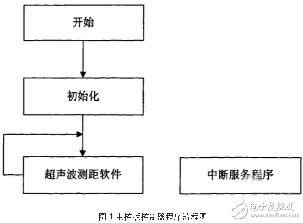
The reset vector address is the program entry and the program is initialized. The initialization includes basic configuration such as expansion mode, overflow mode, DARAM, multiplier, and JTAG. In addition, there are related I/O settings, program-related timer settings, program-related interrupt settings, and serial port communication settings. These configurations are the basic configuration flow used by the controller. After initialization, the relevant interrupt program will be started, and then the ultrasonic ranging program will be entered and cycled. The interrupt service routine is in a ready state, and once an interrupt occurs, the interrupt service routine executes immediately.
In all programs of the TMS320LF2407A, the data transmission and reception procedures of the serial port need to be explained. Asynchronous communication uses three lines (ground, transmit, receive) to connect terminals in RS232 format. The transmit bits are sequentially a start bit, 1 to 8 data bits, an optional parity bit, and 1 to 2 stop bits. Therefore, the maximum data unit that serial communication can transmit is 8 bits, that is, one byte. In the design, the controller and each terminal have various types of data exchange, such as shaping data and floating point data, so data conversion is needed for the data sent and received by the serial port.
Four-byte single-precision floating-point data transfer, because the serial port can only transfer at most one byte at a time, so only need to convert each four-byte floating-point stored data into bytes to send, in the design This is done by means of a forced conversion. When the data is received, the same processing method can be adopted, and the reverse conversion can be performed. In addition, the data conversion can also be implemented by the union, and the essence of the union is the same as the type conversion described above, except that the storage space occupied by each data type of the union is common, and for this storage space, the union definition Any structure type variable can be called. The serial port data processing in the host computer uses this method, which is very convenient.
For the detection of orthogonal coded pulses, the TMS320LF2407A has independent orthogonal coded pulse units. As long as the unit registers are simply set, the running direction and distance parameters of the robot drive wheel can be obtained. TMS320LF2407A sends these data to the host computer through the serial port, which is modeled by the host computer, and the data is processed to obtain the pose information of the robot.
2 motor drive software design
The motor drive software completes the drive control and closed-loop speed regulation of the motor. The drive control uses the on-chip PWM peripheral unit of the motor drive master chip STCl2C4052AD. The generated PWM signal is driven by the motor drive chip to drive the motor. The duty cycle of the 24VDC voltage applied to the motor can be adjusted by adjusting the PWM duty cycle. Thereby adjusting the motor speed. The PWM duty cycle is controlled by an on-chip 8-bit PWM control register. The value range of this register is 0-255, which represents a continuous change of the duty cycle of the PWM signal from l to 0. At the same time, STCl2C4052AD receives the pulse signal of the photoelectric code wheel of the motor, calculates the running speed of the motor by using the on-chip clock, and completes the closed-loop speed regulation of the motor through the speed control algorithm.
The flow chart of the motor drive and closed-loop speed control software algorithm is shown in Figure 2.
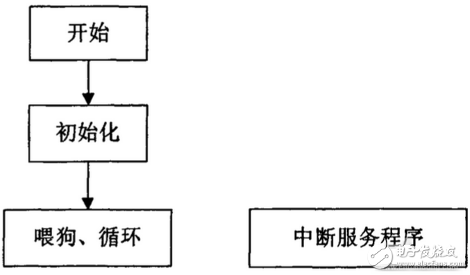
Figure 2 motor drive controller program flow chart
As shown in the figure above, the program is initialized after the start of the program. The initialization includes the program using the relevant variable definition, 10ms timer 0, timer l and serial port, external interrupt 0 for pulse counting, setting of registers such as watchdog, and motor status parameters (brake Initialization of speed, speed, etc. Then enter the loop state, update the relevant flag of the watchdog register during the loop. The speed detection and closed loop speed control procedures are completed in external interrupt 0 and timer 0, respectively. The interrupt service routine also includes external interrupt 0, timer 0, and serial interrupt service routines.
The external interrupt 0 is the pulse detection peripheral of the motor photoelectric code disk, and the pulse of all the motor photoelectric code disks will cause the interruption of the external interrupt 0. The principle of the code wheel pulse speed measurement is to calculate the number of pulses in the STCl2C4052AD unit timing time, so the content of the interrupt service routine of the external interrupt 0 is the pulse count. The target motor speed set by the host computer is also converted to the number of pulses in this unit timing time. You can define a global variable, and each time you enter the interrupt of external interrupt 0, you can add 1 to the variable. In addition, in order to prevent program interference, the count value should be corrected. If it is less than 0, it is equal to 0. When it is greater than a certain set value, it is equal to a certain set value.
3 Ultrasonic ranging software design
The ultrasonic ranging software in the design utilizes the transit time method of common ultrasonic ranging. The working principle of the transit time method is to start timing while transmitting ultrasonic waves, stop timing after receiving ultrasonic waves, and record the transmission time of the ultrasonic waves as t, then the distance between the ultrasonic distance measuring module and the obstacle is s is expressed by the following formula.
S=v*t/2
Where v is the propagation speed of the ultrasonic wave in the air. It is represented by the following formula.
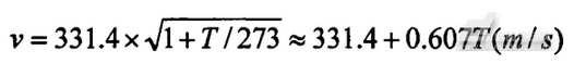
Where T is the Fahrenheit temperature of the air.
At normal temperature, the transmission speed of ultrasonic waves does not change much with temperature, and the transmission time of ultrasonic waves is of the order of milliseconds, so the influence is not great. However, it is also possible to add a temperature correction module to the ultrasonic ranging module to detect the ambient temperature and then correct it when the main board controller calculates the ultrasonic speed. It is now convenient to have integrated temperature sensing devices in the market.
The main flow of ultrasonic ranging is that after the ultrasonic wave is transmitted, if there is a reflected ultrasonic signal return, the calculated distance is received by the external interrupt 0. When the ultrasonic signal is emitted, the timer 3 is turned on, and the timing time is the transmission time required for the maximum ultrasonic measurement distance. If there is no external interrupt 0 interrupt event when the timer 3 is interrupted, that is, no reflected ultrasonic signal is returned, then When the timer 3 is interrupted, the ultrasonic return interrupt and the ultrasonic transmission time timer l are turned off, and the next ultrasonic ranging cycle is performed. The program flow chart is shown in Figure 3.
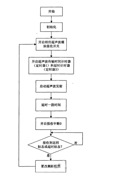
Figure 3 ultrasonic ranging program flow chart
When the external interrupt 0 receives the ultrasonic ranging signal return, it enters the external interrupt 0 service program to perform the ranging program processing. If there is no ultrasonic signal return, the timer 3 timer interrupt will occur, indicating that the waiting timeout is set, and the obstacles in the ranging range are set. In both cases, the wait flag bit will be changed, the program jumps out of the wait state, and the working ultrasonic ranging module is changed to perform the ranging processing of the next ultrasonic module.
The program flow chart of external interrupt 0 and timer 0 is shown in Figure 4.
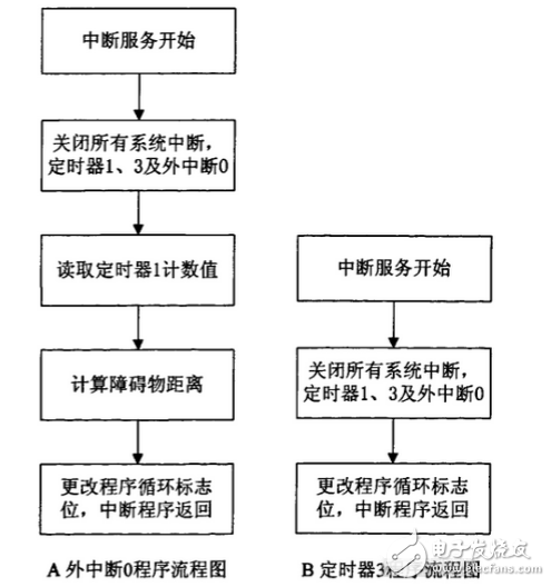
Figure 4 external interrupt 0 and timer 3 program flow chart
In the figure, A is a flow chart of the external interrupt 0 program. Entering the interrupt service routine indicates that an ultrasonic signal is returned. The program starts to turn off all system's maskable interrupts and ranging using peripherals, reads the timer l count value, and calculates the obstacle distance. Change the program loop flag and then return the service routine to return. B is a program flow chart of the timer 3. Entering the interrupt service program indicates that there is no obstacle in the ranging range. Therefore, only use the peripherals that can be masked interrupt and ranging to shut down the system, directly change the program loop flag, and exit the interrupt service routine. Setting Timer 1 does not generate an interrupt, and setting Timer 1 to the timing maximum does not cause a Timer 1 interrupt. Therefore, it is not necessary to write the interrupt service routine of timer 1.
4 Conclusion
The main control board controller coordinates the work of the upper computer and each module, and the software design details the data type processing problem in the serial port transmission. The single-chip PWM peripheral is used to generate the pulse width modulation signal to drive the motor, and the closed-loop speed regulation of the motor is realized by the photoelectric code disk. The ultrasonic ranging module has been widely used. The ultrasonic ranging module software program uses the universal transit time method to complete the distance measurement, and realizes the time sharing of the multi-ultrasonic ranging module through the analog switch.
Wuxi Doton Power , https://www.dotonpower.com