A single-phase AC motor is a type of electric motor that converts electrical energy into mechanical energy, or vice versa. It operates on a single-phase alternating current supply and is widely used in household appliances and small industrial equipment due to its simplicity and cost-effectiveness.
Working Principle of Single-Phase AC MotorsSingle-phase motors typically have two windings: the main winding (running winding) and the auxiliary winding (start winding). These windings are positioned at a 90-degree angle relative to each other in space. To create a rotating magnetic field, a capacitor is connected in series with the start winding. This capacitor causes the current in the start winding to lead the current in the running winding by 90 degrees. As a result, two pulsating magnetic fields are created, which combine to form a rotating magnetic field in the air gap between the stator and rotor.
This rotating magnetic field induces an electromotive force in the rotor, causing a current to flow through it. The interaction between this induced current and the rotating magnetic field generates a torque that causes the motor to rotate.
Single-Phase AC Motor Working Principle DiagramThere are several common starting methods for 220V single-phase motors, each with its own advantages and applications.
1. Split-phase Starting Type: This method uses an auxiliary winding along with a centrifugal switch. The starting torque is relatively low, but it is sufficient for light-load applications such as fans, air conditioners, and washing machines. Figure 1 shows the wiring configuration for this type of motor.
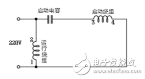
Figure 1: Capacitor-start type wiring circuit
2. Capacitor Start Type: In this method, a starting capacitor is connected in series with the auxiliary winding. When the motor is powered on, the capacitor helps increase the starting torque. Once the motor reaches about 70–80% of its rated speed, the centrifugal switch disconnects the starting capacitor from the circuit. The motor then continues to run using only the main winding. This type is commonly used in applications like compressors and woodworking machines. Figure 2 illustrates the wiring diagram for this configuration.
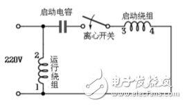
Figure 2: Capacitor start type wiring circuit
3. Capacitor Start and Run Type: In this configuration, both a starting capacitor and a running capacitor are used. The starting capacitor provides high initial torque, while the running capacitor remains connected during operation to improve efficiency. This method is ideal for heavy-duty applications such as air compressors and cutting machines. Figure 3 shows the wiring for this setup.
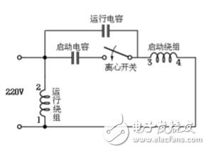
Figure 3: Capacitor start-up type wiring circuit (double capacitor)
It's important to note that if a motor with a centrifugal switch fails to start within a short time, the windings may overheat and burn out. The capacitance values vary depending on the motor type—starting capacitors usually have larger capacities than running capacitors, and they must be rated for voltages above 400V to ensure safe operation.
Forward and Reverse ControlFigure 4 shows a simple forward and reverse control circuit for a single-phase motor. In this design, the start and run windings have similar resistance values, meaning they are often identical in wire size and number of turns. This makes it easy to reverse the direction of rotation by switching the connection of the start winding. This method is commonly used in washing machines, where directional control is necessary. The control system is straightforward and does not require complex switches.
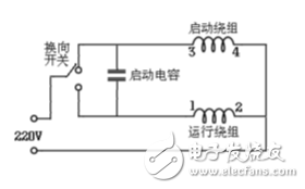
Figure 4: Forward and reverse control wiring
| Model | Nominal Voltage | Nominal Capacity | Nominal impedance | Dimension | Charge-discharge standard | Approx Weight | |||
| (V) | (mAh) | (mQ) | Diameter | Height | Charge | Discharge | ≈g | ||
| ICR10220 | 3.7 | 130 | <150 | 10 | 22 | 0.5C-1C | 0.5C-1C | 4.1 | |
| ICR10440 | 3.7 | 350 | <120 | 10 | 44 | 0.5C-1C | 0.5C-1C | 9 | |
| ICR14430 | 3.7 | 650 | <100 | 13.8 | 42.8 | 0.5C-1C | 0.5C-1C | 17 | |
| ICR14500 | 3.7 | 900 | <80 | 14 | 50 | 0.5C-1C | 0.5C-1C | 19.5 | |
| ICR17280 | 3.7 | 600 | <100 | 16.3 | 28 | 0.5C-1C | 0.5C-1C | 15 | |
| ICR17335 | 3.7 | 700 | <100 | 16.3 | 33.5 | 0.5C-1C | 0.5C-1C | 18 | |
| ICR18500 | 3.7 | 1400 | <70 | 18.1 | 50 | 0.5C-1C | 0.5C-1C | 33 | |
| ICR18650 | 3.7 | 2000 | <50 | 18.1 | 64.8 | 0.5C-1C | 0.5C-1C | 45 | |
| ICR18650P | 3.7 | 2000 | <40 | 18.1 | 65 | 0.5C-1C | 3C-5C | 45 | |
| ICR18650P | 3.7 | 2200 | <40 | 18.1 | 65 | 0.5C-1C | 3C-5C | 45 | |
| ICR18650 | 3.7 | 2600 | <70 | 18.1 | 64.8 | 0.5C-1C | 0.5C-1C | 45 | |
| ICR26650 | 3.7 | 3500 | <30 | 26 | 65.5 | 0.5C-1C | 0.5C-1C | 85 | |
| ICR26650P | 3.7 | 5000 | <30 | 26 | 65.5 | 0.5C-1C | 0.5C-1C | 85 | |
| ICR18650P | 3.7 | 1500 | <15 | 18.1 | 64.8 | 1C | 10C-15C | 47 | |
| ICR26650P | 3.7 | 2200 | <15 | 26 | 64.8 | 1C | 10C-15C | 64 | |
| IFR14430E | 3.2 | 400 | <115 | 13.8 | 43 | 0.5C-1C | 0.5C-1C | 15 | |
| IFR14500E | 3.2 | 400 | <95 | 13.8 | 50.2 | 0.5C-1C | 0.5C-1C | 15.5 | |
| IFR14500E | 3.2 | 650 | <80 | 13.8 | 50.2 | 0.5C-1C | 0.5C-1C | 17.8 | |
| IFR18500E | 3.2 | 600 | <80 | 18 | 50 | 0.5C-1C | 0.5C-1C | 19.5 | |
| IFR18500E | 3.2 | 1200 | <80 | 18 | 64.8 | 0.5C-1C | 0.5C-1C | 30.4 | |
| IFR18650E | 3.2 | 1500 | <65 | 18 | 64.8 | 0.5C-1C | 0.5C-1C | 40.5 | |
| IFR18650E | 3.2 | 1700 | <80 | 18 | 65.3 | 0.5C-1C | 0.5C-1C | 41.2 | |
| IFR26650E | 3.2 | 3400 | <20 | 26 | 65.3 | 0.5C-1C | 0.5C-1C | 87 | |
| IFR18650P | 3.2 | 1100 | <20 | 18 | 65.3 | 1-3C | 10-25C | 40 | |
| IFR26650P | 3.2 | 2400 | <20 | 26 | 65.3 | 1-3C | 10-25C | 82 | |
Cylindrical Battery,Cylindrical Shell Method,Cylindrical Batteries,Cylindrical Battery Cells
Langrui Energy (Shenzhen) Co.,Ltd , https://www.langruibattery.com