A single-phase AC motor is a type of electromagnetic rotating machine that converts electrical energy into mechanical energy, and vice versa. These motors are widely used in household appliances and industrial equipment due to their simplicity and cost-effectiveness.
**Working Principle of Single-Phase AC Motors**
Single-phase capacitive motors have two windings: the starting winding and the running winding. These windings are placed 90 degrees apart in space. A large capacitor is connected in series with the starting winding. When the motor is powered, the current through the starting winding leads the current in the running winding by 90 degrees because of the capacitor’s effect. This phase difference creates two pulsating magnetic fields that combine to form a rotating magnetic field in the air gap between the stator and rotor.
This rotating magnetic field induces a current in the rotor, which then interacts with the magnetic field to produce torque. As a result, the motor begins to rotate.
**Working Principle Diagram of Single-Phase AC Motor**
There are several methods for starting a 220V single-phase motor. One common method is the split-phase start, as shown in Figure 1. This method uses an auxiliary winding to assist in starting, but it provides limited starting torque. Once the motor reaches its operating speed, the auxiliary winding is disconnected. This type of motor is often found in electric fans, air conditioners, and washing machines.
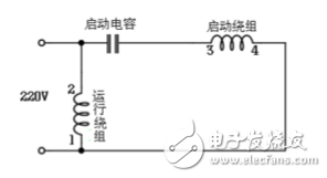
*Figure 1: Capacitor transfer type wiring circuit*
Another method involves a starting capacitor, which is connected during startup and automatically removed once the motor reaches about 70% to 80% of its rated speed. This is known as the capacitor-start method, as illustrated in Figure 2. The starting capacitor helps provide higher starting torque, while the running winding continues to operate once the motor is up to speed.
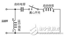
*Figure 2: Capacitor start type wiring circuit*
In some applications, such as air compressors or woodworking machines, a dual capacitor system is used. Here, a starting capacitor is used during startup, and a smaller running capacitor remains connected during operation. This configuration improves performance under heavy loads. This setup is shown in Figure 3.
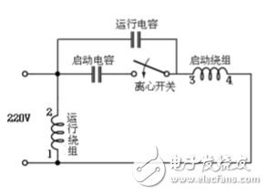
*Figure 3: Capacitor start-up type wiring circuit (double capacitor)*
It's important to note that if a motor with a centrifugal switch fails to start within a short time, the windings can overheat and burn out. The capacitance values vary depending on the application—starting capacitors typically have larger capacities than running capacitors, and they must be rated for voltages above 400V.
**Forward and Reverse Control**
Figure 4 shows a wiring diagram for forward and reverse control. In this setup, the starting winding has the same resistance as the running winding, meaning both windings are identical in terms of wire size and number of turns. This design is commonly used in washing machines, where simple switching is sufficient for reversing the motor direction without complex switches.
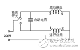
*Figure 4: Switch control for forward and reverse*
Understanding these principles helps in selecting the right motor for different applications and ensures proper maintenance and troubleshooting.
Langrui Energy (Shenzhen) Co.,Ltd , https://www.langruibattery.com