Non-contact inductive power supply combines electronic power technology and electromagnetic induction coupling technology, and has been widely used in electric vehicles, mobile phone charging and robotics. Through the analysis of the structure and principle of the non-contact inductive power supply system, the key technologies such as compensation of the primary and secondary circuits and frequency selection are studied, and the calculation methods of the primary and secondary compensation capacitors are obtained. According to the power supply requirements of the torque test, the specific circuit was designed and the output voltage of the design circuit was tested. The results show that the power supply circuit can meet the power supply requirements of the torque test within a certain distance range, which provides a new idea for the torque test power supply.
0 Preface
Currently, there are two main methods for providing energy to a rotating torque test system: slip ring power supply, battery power supply. The slip ring power supply adopts the sliding contact between the brush and the collector ring. In use, there are limitations such as sliding wear, contact spark, carbon accumulation and unsafe bare conductor. The battery power supply has limited power and high requirements for the power supply environment. The shortcomings and shortcomings make these two power supply methods unable to meet the needs of torque testing, so it is especially important to study a way to supply power to the rotating shaft torque test system. The development of contactless inductive power supply technology has provided a new direction for power supply for rotary shaft torque testing.
The non-contact induction power supply combined with the electronic power technology and the electromagnetic induction coupling technology realizes the power transmission without physical connection or contact, and overcomes the shortcomings and shortcomings of the traditional power supply mode, thereby ensuring the safety and reliability in the transmission process. Compared with the traditional transformer induction power supply, the non-contact induction power supply is a loosely coupled power supply. By adopting the primary and secondary side resonance compensation technologies and controlling the output current frequency of the power supply, the transmission performance is improved and the cost is reduced.
Foreign research on this technology began in the 1970s, and has made some progress. The research on the development of contactless power supply system projects is still in progress, and domestic research in this field is still blank.
1 Non-contact induction power supply system structure and principle
The non-contact inductive power supply system uses the principle of electromagnetic induction to achieve energy transfer through non-contact coupling. Figure 1 shows the energy transfer block diagram.
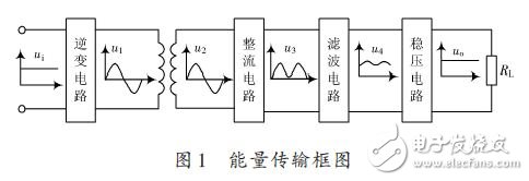
The system converts the direct current into a high-frequency equal-amplitude AC signal to drive the primary winding through the inverter circuit, so that it generates an electromagnetic field with a small magnetic field strength but a high frequency variation in a certain range of space around. The secondary winding is located in the electromagnetic field, and the high-frequency variation of the magnetic flux of the secondary winding causes a high-frequency induced electromotive force of a certain amplitude in the secondary winding. After rectification, filtering, and voltage regulation, a DC power having a certain driving capability can be obtained for the torque test. provide energy. There is no direct contact between the primary winding and the secondary winding of the inductive power supply system, enabling wireless transmission of electrical energy.
The power supply system is different from the traditional transformer inductive energy transmission system. The coupling performance between the primary and secondary side groups is poor, and it is in a loosely coupled state. The leakage inductance cannot be ignored. The original and secondary winding voltages do not satisfy the proportional relationship of winding turns. . In order to improve system performance and improve system power transmission capability, this paper establishes a mutual inductance model and uses resonance compensation technology for the primary and secondary windings respectively. The secondary side compensation can effectively improve the transmission power of the system. The primary side compensation can effectively improve the power factor of the primary side and reduce the apparent power requirement for the DC power supply.
1.1 Mutual inductance model of non-contact inductive power supply system
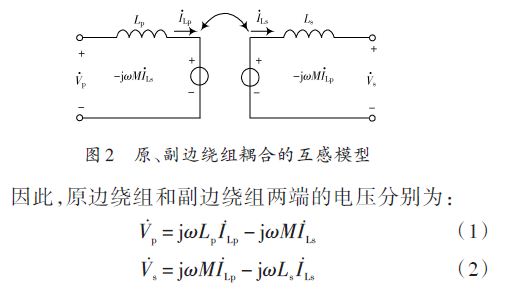
The mutual inductance model of the non-contact original and secondary winding couplings is shown in Figure 2, ignoring the resistance of the primary and secondary windings. In the figure, Vp and Vs respectively represent the primary and secondary winding voltages of the non-contact inductive power supply system. Lp and Ls represent the primary and secondary inductances respectively, M represents the mutual inductance of the primary and secondary windings, and ω is the inverter. Current angular frequency, original and secondary winding currents I-Lp, I-Ls reference direction as shown. jωMI-Lp represents the induced voltage of the primary winding current I-Lp on the secondary winding, and -jωMI-Ls is the reflected voltage of the secondary winding current I-Ls on the primary winding.
1.2 Original and secondary compensation
1.2.1 Secondary compensation
In the loosely coupled inductive power transfer system, if the secondary side has no compensation circuit and the secondary winding is directly connected to the load of the resistance R, the secondary side output voltage Uo, the output current Io, and the output power Po are respectively:
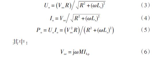
From equations (3) to (6), the output voltage and current of the system vary with the magnitude of the load, limiting the power output. To this end, the secondary winding must be effectively compensated. As shown in Figure 3, the basic compensation topology has two forms: capacitor series compensation and capacitor parallel compensation.
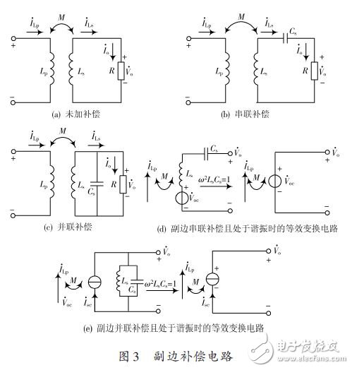
In Figure 3(b), the compensation capacitor Cs and the secondary inductor Ls are at the resonant frequency, and the secondary side is equivalent to a pure resistor. The output voltage is independent of the load and is equivalent to a constant voltage source whose output voltage is the secondary induced voltage. Fig. 3(d) shows an equivalent conversion circuit in which the secondary side is series-compensated and is in resonance, and V-oc is the secondary winding induced voltage.
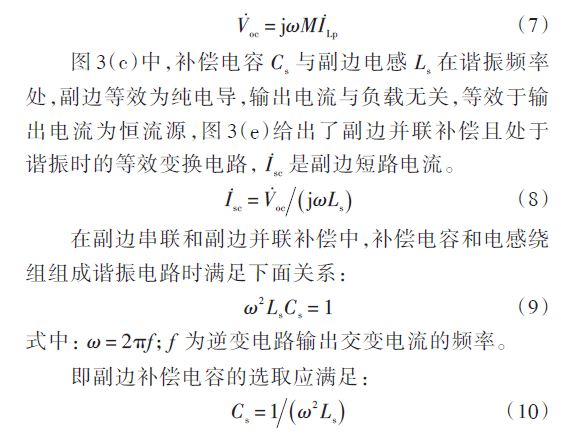
In actual operation, the secondary compensation circuit is not necessarily in a fully resonant state, but the closer to the resonant state, the better the output characteristics of the circuit.
JoyLED outdoor LED display is 50% lighter than traditional Led Advertising Panel, which saves transportation and labor cost.
Patented light-blocking design of JoyLED outdoor fixed LED screen prevents light leakage to the front. Led Display Modules support for front and rear maintenance. The handle design brings convenience to LED panel lifting. Great heat dissipation and IP65 protection grade for JoyLED Outdoor Fixed LED Display. Front Maitenance Illustration for LED display.

Outdoor Fixed LED Display
Large Led Display,Led Video Panels,Led Display Board ,Led Fixed Outdoor Display
Shenzhen Joy LED Display Co., Ltd. , https://www.joe-led.com