The existing heaters are mostly heated by conventional devices such as electric heating pipes and electric heating wires. The outer shell of the electric heating pipes is a steel pipe made of stainless steel and has a heating element resistance wire. When it is heated, the resistance wire and the steel pipe transfer heat to the outside, when the air is not When flowing, the heat of the heating pipe will not be able to dissipate, and the temperature will become higher and higher. In serious cases, the heating pipe will be burned and even a fire may occur. The PTC thermistor as a heating material, with energy-saving constant temperature, no open flame, good security, easy to adjust the amount of heat, the impact of the power supply voltage fluctuations, rapid heating and so on, so the design of the use of PTC thermistor heating material The constant temperature heating system is of great significance for applications requiring a high degree of safety.
2, the overall design of the system
The system uses AT89C2051 as the control core, PTC thermistor to heat the heating area, digital thermometer DS18B20 real-time acquisition temperature, set by the peripheral keyboard to heat the upper and lower limit of the temperature value, through the real-time acquisition of the temperature value and set Comparison of temperature value, to determine whether to reach the set temperature range, by AT89C2051 control multiple relays to achieve multiple PTC thermistor (one relay control a PTC thermistor) working state of the switch control, so that the heating zone temperature is maintained Within the set temperature range. System schematic shown in Figure 1.
3, SCM control heating
3.1 SCM system
AT89C2051 is a low-voltage, high-performance CMOS 8-bit single-chip microcomputer produced by ATMEL Corporation of the United States. It is produced by ATMEL's high-density, non-volatile memory technology and is compatible with the MCS-51 instruction system. The chip has a built-in general-purpose 8-bit CPU and 2K. Byte Flash Flash Memory, 128 bytes internal RAM, 15 I/O lines, 2 16-bit timer/counters, 1 5-vector two-level interrupt structure, 1 full-duplex serial communication port, built-in 1 A precision comparator, on-chip oscillator and clock circuit [1].
3.2 PTC Thermistors
PTC is the English abbreviation of Positive Temperature Coefficie-nt, which is a positive temperature coefficient, and its resistance value increases with increasing temperature. Before the PTC thermistor does not reach a specific temperature, the resistance of the resistor changes very slowly with temperature. When the temperature exceeds this temperature, the resistance of the PTC thermistor increases sharply, and the temperature at which the resistance changes drastically changes. For the Curie temperature, it is an important technical indicator of the PTC thermistor [2].
Figure 2 shows the current-time characteristics of the PTC thermistor.
3.3 digital thermometer DS18B20
The DS18B20 digital thermometer is a 1-Wire device manufactured by DALLAS. It is a single-bus device and features a simple circuit and small size. The measurement temperature range is -55°C to +125°C, and the accuracy is ±0.5°C in the range of -10°C to 85°C. The DS18B20 has an accuracy check of ±2°C. The on-site temperature is directly transmitted in the “one-line bus†digital mode, which greatly improves the system's immunity to interference.
Since the DS18B20 uses the 1-Wire bus protocol mode, which means that data is transmitted in both directions on one data line, the single-bus protocol is not supported on the hardware of the AT89C2051 single-chip microcomputer. Therefore, software must be used to simulate the single-wire bus. The protocol timing of the bus completes the access to the DS18B20 chip. The protocol defines the timing of several signals: initialization timing, read timing, and write timing. All timings use the host as the master device and the single-bus device as the slave device. The transmission of data and commands is low-priority [3].
3.4 Microcontroller Control Multiple Relays
SCM control relay shown in Figure 1, the figure shows only one way the relay control circuit connection, it takes up a single-chip P3 port, multi-channel relay can be achieved through the use of different pins, the system uses P3 port 3 Bit control 3 relays. The PTC thermistor uses DC 12V and the voltage is provided by the switching power supply. Because the drive current of the single-chip P3 port is 20mA, and the drive of the relay is equivalent to the drive of the high-power device for the single-chip microcomputer, the drive current of the P3 port must be amplified, and the PTC thermistor is powered by the direct current 12V voltage, and may be to the microcontroller The stability of the operation has an influence, so the use of optocoupler 4N33 to improve the driving capacity of P3, and because the optocoupler 4N33 is the application of electro-optical-electrical conversion form to amplify the drive current, so that the isolation of the microcontroller and the relay, eliminating the The system may be potentially unstable. When the port of the single-chip microcomputer P3 is connected to the pin of the relay to a low level, the LED of the 4N33 input is turned on, and the output terminal outputs the amplified current to drive the relay to pull in, so that the PTC thermistor loop is conducted and the heating starts [4- 5].
The PTC thermistor has an inrush current at the beginning of its operation. From its current-time characteristics (as shown in Figure 2), it can be seen that after a certain period of time, the current drops to a stable operating state. At this time, the current Very small, about 0.8 ~ 1A, so when you start heating, you can not open the three relays at the same time for heating, because the PTC thermistor power supply is DC 12V, 12A, if you open the three-way relay at the same time, in the PTC When the thermistor's inrush current reaches the maximum value (5.7 to 7A), the current drawn by the switching power supply exceeds its rated value, causing the power supply to stop working and even destroy, which affects the continuity and reliability of the system operation. In view of this factor, the time from the start of the operation of the monolithic PTC thermistor to its maximum value, S1, and the time S2 from the maximum value to below 4A are measured. This determines the opening of the relay based on these two times. . The three-way relays are set to be 1, 2, and 3 respectively. After the microcontroller is powered on, the first relay is turned on, and after the current passes from the minimum value to the maximum time S1, the second relay is turned on (if the first The temperature provided by the PTC thermistor does not reach the set temperature range. The opening of the third relay also takes time S1. The on/off status of each relay is determined by the comparison between the real-time temperature measured by the digital thermometer DS18B20 and the upper and lower limits of the set temperature. The sequence of the relay's opening is set to 1, 2, and 3, and the shutdown sequence is set. Set to 3, 2, 1, these settings are implemented by software.
3.5 Keyboard, Display
The peripheral keyboard of this system adopts HD7279A keyboard display chip. Because it is necessary to display the upper and lower limits of the system set temperature and the real-time heating temperature, only the keyboard function of HD7279A is used. The display part of the system uses the LT12864I liquid crystal display module. When the system starts to work, set the heating temperature through the keyboard, the data is transmitted to the SCM, and then the data is sent to the display module by the SCM; during the system work, the real-time temperature value measured by the digital thermometer DS18B20 is also transmitted to the SCM, and then The microcontroller converts the data and sends it to the display module [6-7].
4, system software design
The overall system software flow chart shown in Figure 3. After the system is powered on, it is initialized first and the registers and I/O ports are set. When the key valid signal is detected, the key data is read, passed to the MCU and sent to the display module. After the keyboard is set, the flag is set. After the MCU detects the signal, the first relay is turned on for heating. At this point, the digital thermometer DS18B20 is initialized for temperature measurement, and the measured real-time temperature data is sent to the SCM for processing and displayed by the display module. DS18B20 compares the measured temperature value with the upper and lower limits of the set temperature value after each measurement of the temperature. If the actual measured temperature is higher than the upper limit of the set temperature, go to the relay closing process to check the opening of each relay. Off state, turn off the relays in the order of the 3rd, 2nd, and 1st way (one relay is turned off for each execution); if the measured temperature is lower than the lower limit of the set temperature, go to the relay turn-on process and check each All relays are opened and closed according to the sequence of the 1st, 2nd, and 3rd relays (each relay is turned on to open 1 relay). In the subsequent work of the system, the cycle-by-cycle temperature-to-temperature comparison-opening or closing of relays is always performed so as to achieve the purpose of constant temperature control of the heating zone.
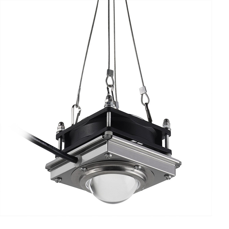
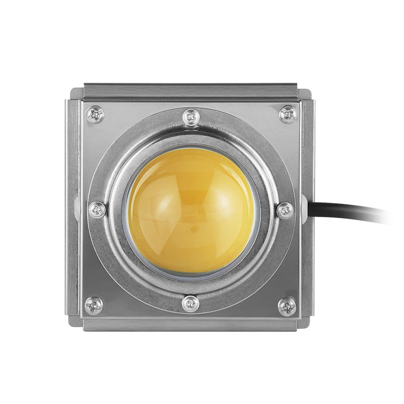
2020 Hottest Cob Grow Light diy model, 200w grow light , cob grow light, high power grow light, etc.
Can also do OEM/ODM service, More cob Led Grow Lamp is a great ideal for all kinds of indoor garden plants: lettuce, orchid, organic herbs, pepper, strawberries, succulent, hydroponic, medical plants.
Whether it's hydroponics, plants in soil, you can add a touch of magic to every veg and flower with Xeccon grow lights.


Cob Grow Light,Best Cob Led Grow Light ,Grow Light Cob Diy,Diy Grow Light
Shenzhen Wenyi Lighting Technology Co., Ltd , https://www.wycngrow.com