By utilizing the built-in input and output points of a PLC, it's possible to expand the actual number of input points without adding extra hardware. This approach enhances the cost-effectiveness of the system. Both methods introduced in this article have been tested in the lab, proving to be reliable, easy to understand, and highly applicable in real-world scenarios.
1. Introduction
PLCs are widely used in industrial control due to their compact size, high cost-performance ratio, low power consumption, strong anti-interference capability, and ease of programming. However, in practical applications, the number of input points required for a task may exceed the available ones, while the output points are often sufficient. To address this imbalance, several strategies can be employed:
1) Adding dedicated input modules increases the system cost and reduces efficiency. 2) Using a PLC with more input points can lead to unused output points, causing resource waste. 3) Incorporating peripheral circuits such as decoders can reduce initial investment. 4) A software-based approach allows expanding input points using existing PLC resources without additional hardware, making it an efficient solution.
This paper introduces two software-based methods for expanding PLC input points by leveraging both input and output points.
2. Software-Based Input Point Expansion Method
One key feature of PLCs is that their input and output points are independent, allowing flexible combinations. By applying matrix keyboard scanning principles or input node combination matrices, we can effectively increase the number of input points.
2.1 Expanding Input Points Using Matrix Keyboard Scanning
By using m input points as row lines and n output points as column lines, we can create a matrix that enables the detection of up to m × n input points. The PLC controls the column lines, while the row lines detect the state of the input nodes. This method is particularly useful when there are spare output points available.

Figure 1 illustrates a 4×2 input expansion using this principle. When y0 is active, only s0 is detected; when y1 is active, s1 is detected. This process ensures that each input node can be uniquely identified based on the state of the output and input lines.
The scan time depends on the PLC type—shorter for transistor or solid-state outputs, and longer for relay outputs to avoid contact wear.
2.2 Expanding Input Points Using Input Node Combination Matrix
When no output points are available, an alternative is to use a combination matrix. By grouping m input points and connecting them to n detection terminals, we can expand the total number of input points to m × n. Diodes are used to prevent signal interference between nodes.

In Figure 2, three input groups and four detection terminals allow the identification of eight unique input nodes. When s0 closes, signals appear at x0 and x6, indicating its status. This method is highly adaptable and suitable for most PLC systems.
3. Conclusion
Using the internal input and output points of a PLC to expand the number of input points without additional hardware improves system cost-efficiency. Both methods have been validated in laboratory settings, demonstrating reliability, simplicity, and significant application value in industrial automation systems.
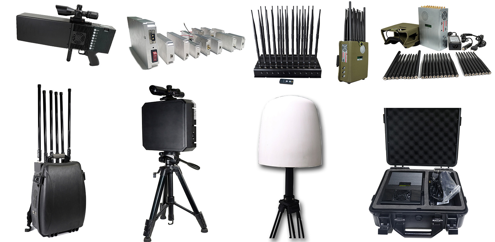
UAV Drone Jamming Module Jammer
The specific principles include:
1. Electromagnetic interference: By emitting powerful electromagnetic signals, it interferes with the communication system of the UAV, making it unable to communicate with the ground control center or operators normally, thus making the UAV out of control.
2. GPS jamming: By transmitting jamming signals, it interferes with the UAV's Global Positioning System (GPS) receiver, making it unable to accurately obtain its own position information, thus causing the UAV to be unable to navigate and locate.
3. Wireless signal interference: By transmitting interference signals, it interferes with the wireless communication signals of the UAV, making it impossible to receive or send wireless signals, thus affecting the control and command transmission of the UAV.
4. Radar jamming: By transmitting jamming signals, it interferes with the radar system of UAV, making it impossible to accurately detect the surrounding environment, thus affecting the navigation and obstacle avoidance ability of UAV.
5. Thermal interference: By emitting a high-energy laser beam or microwave beam, the UAV is attacked by thermal energy, so that its key components are damaged or invalid, thus making the UAV unable to operate normally.

Drone Jammer,UAV Drone signal blocker,Jammer Module,UAV Drone Jamming Module,Drone amplifer modules,signal jammers
Yetnorson Antenna Co., Ltd. , https://www.yetnorson.com