As the 4G LTE network is gradually rolled out globally, its data transmission speed is higher than that of the cellular 3G system, but because it uses overlapping frequency bands, a new intermodulation interference source (IMsource) is generated, which brings about increasingly severe interference problems. The existing test protocol focuses on the intermodulation products generated by the two carrier signals, but there are actually multiple modulation carrier problems. For a carrier of X (MHz) modulation bandwidth, the third-order intermodulation products will exhibit 3 times the modulation bandwidth and spread throughout the receiver's noise floor. According to the rule of thumb, the receiver's noise floor will increase by 20 times, and its effective coverage area will be reduced by 10 times. Clearly, this has a significant impact on return on investment (ROI) and quality of service (QoS).
The LTE network itself generates some noise interference, but the 4G test protocol is considered more broadly, including co-site interference generated by blocking signals from non-LTE networks (GSM, UMTS, etc.). Since network coverage and data throughput are severely affected by the Noise Signal Interference Ratio (SNIR), the LTE protocol requires rigorous testing of the entire component supply chain. From power amplifiers and transceiver chipsets to tunable capacitors for impedance matching networks and a variety of passive components, suppliers will have a strategic competitive advantage if they can meet intermodulation metrics and provide intermodulation test data. In the absence of such test equipment, engineers from various positions in R&D to production will be forced to build their own test systems.
The degree of nonlinearity of each device will affect the level of intermodulation of the system. During measurement, the performance of the system to be built or the system to be maintained can be simulated and optimized one by one, including space scheme, device isolation, guard band, device selection, and so on.
A test system that traditionally uses two equal-power transmit carriers measures third-order intermodulation products that fall within the receive band, primarily for in-band interference testing. But for 4G networks, the main sources of intermodulation include blocking signals, such as the second harmonic generated by single carriers of low-frequency devices (UHF transmitters, TVs, GPS, etc.), as well as in-band transmit signals and non-LTE communication platforms. The second-order and third-order intermodulation products generated by the interference signal.
This paper describes the RF filtering module system of the test system. As the number of frequency bands increases, these system modules can be flexibly inserted (extracted) into the system to provide testing based on multiple LTE bands. Customizable test modules and flexible overall system design enable intermodulation testing based on a mixture of two signals or multiple signals.
Passive Intermodulation (PIM) and Intermodulation (IM)
Although "Passive Intermodulation (PIM)" and "Intermodulation (IM)" are often used interchangeably, in reality, passive intermodulation products are caused by improper production and installation processes, such as poor solder joints, Metal-to-metal bonding, magnetic materials, flawed surface treatment, and the like. These problems, in essence, are not very correlated with frequency, so we can perform passive intermodulation testing of passive products (cables, connectors, etc.) using single-band rather than multi-band. The industry consensus is that based on two +43dBm carrier inputs, the passive intermodulation values ​​of passive components should reach -156dBc~-169dBc. In order to meet the dynamic range of qualified test equipment, the input carrier is prevented from being reflected back to the source, as this reflection will increase the system noise floor.
In contrast, intermodulation products (IM) are brought about by nonlinear devices such as PIN diodes, transistors, tunable BAW/SAW filters, MEMS capacitors, and the like. It is highly dependent on frequency, so the intermodulation test must be performed on a multi-band basis, especially based on the specified operating band. From a numerical point of view, the industry's current intermodulation level (IMD) is not as stringent as the passive intermodulation level (PIM), but as the carrier power level increases, the gap between the two is shrinking.
IP3 and intermodulation testing
For general devices under test, the cause of nonlinearity leading to intermodulation products is covered in many literatures. From the perspective of setting up a test set, the wider the dynamic range required (usually the intermodulation index plus 10 dB), the more attention needs to be paid to prevent newly generated intermodulation products and reflected energy from entering the device under test. The following are industry-recognized typical LTE band-based intermodulation levels:
â— High-power passive components of wireless base stations: -113dBm under two +43dBm carriers;
High-power passive components of distributed antenna system (DAS): -118dBm at two +43dBm carriers;
â— High-power passive components of passive intermodulation analyzer: -127dBm under two +43dBm carriers;
â— Small power broadband switch, MEMS capacitor, transceiver chipset and adjustable device: up to -140dBm for two +26dBm carriers (in many cases, the first carrier is the transmission band and the second is the blocking band).
The conversion between the third-order intercept point (IP3) and the intermodulation distortion (IMD) is as follows (unit: dBm): IP3=P+IMD/2, where IMD is the third-order intermodulation distortion and two P-power carriers The difference.
Case 1:
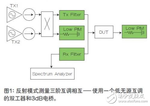
A commonly used test system (shown in Figure 1) contains two transmit signals from the downlink (DL) band and produces third-order intermodulation distortion in the receive band. In this system, the power amplifier and low intermodulation 3dB bridge are easier to obtain, and the isolator is relatively cheap, which brings convenience and economy, but this widely used solution has a narrow dynamic range.
The amplifier has 50dB isolation through the isolator and 3dB bridge. Based on the return loss of the device under test, the two transmitted signals are reflected back to the coupler and evenly distributed between the Tx1 and Tx2 ports. Since the isolator is a magnetic device, it will create new intermodulation distortion and produce high intermodulation products at the coupler. Therefore, the Tx filter must have more than 100dB of rejection in the receive band, preventing these intermodulation products from entering the Rx filter, while the amplifier needs to generate more than 3.5dB of gain to offset the losses caused by the isolator and coupler. The greater the return loss of the device under test, the more limited the dynamic range of the device.
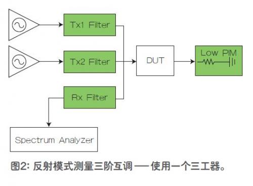
Case 2:
In Figure 2, the amplifier produces approximately 75 dB of isolation through two bandpass filters. The device under test is connected to a low passive intermodulation load, and the third-order intermodulation products can be read on the spectrum analyzer through the receive filter. The system can be fixed by one carrier and another carrier to obtain more data points. In the system periodic calibration, the common port of the triplexer is connected to the load, and the third-order intermodulation is measured by the receiving filter to verify the reference level of the system. It is recommended to use low passive intermodulation connectors to protect RF ports that require frequent connections, as multiple connections may create more passive intermodulation problems. It is also recommended to use a DIN (7/16) connector on the common port for better durability and lower surface current. The remaining three connectors are not particularly critical and they do not affect the passive intermodulation level of the device because the two large carriers of the input do not occur at the same time.
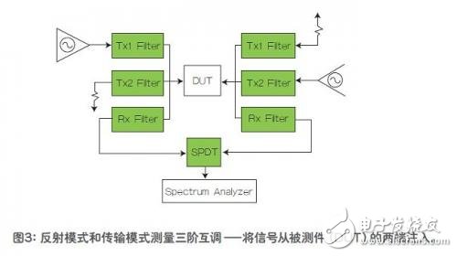
Case 3:
In FIG. 3, a transmission test or a reflection test of the third-order intermodulation can be performed by injecting signals from both ends of the device under test. Tx1 represents a large signal from the transmit band, and Tx2 represents any signal that can be mixed with Tx1 and produce passive intermodulation products in the receive band, as in the second order case, IM=Tx1-Tx2.
KCC Certificate Extension Sockets
England Power Socket,Silver Wall Sockets,Wall Switches And Sockets,Wall Socket With Usb Charging Ports
Heikki Technology Co., Ltd. , https://www.heikkipower.com