1. Introduction
The traditional radar transmitter relies on a dedicated signal generation module, which is limited in its ability to randomly configure waveform forms, parameters, signal center frequency, and power levels. This restricts the system's flexibility and broad application potential. Especially during the pre-research and technology exploration phases of radar systems, there is a need to experiment with and evaluate various radar signals. Designing a separate signal generator for each type of radar signal would be extremely costly. To address this issue, virtual instrument technology offers a promising solution by integrating high-performance commercial test instruments [1]. Using the programming capabilities of a virtual instrument system, it becomes possible to simulate a wide range of radar signals with greater flexibility in parameter settings, thereby enhancing the system’s versatility and meeting diverse application requirements.
2. Radar Signal Generation System
The principle of radar signal generation is illustrated in Figure 1. The baseband signal generation module converts digital stored waveforms into two I/Q analog baseband signals using D/A conversion. These I/Q signals are then modulated with orthogonal carriers in the I/Q modulation module, shifting the signal’s center frequency to the RF or microwave band. The final output is the desired radar signal.
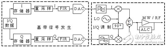
Figure 1. Schematic diagram of radar signal generation
3. Radar Signal Simulation System Based on Virtual Instrument During the pre-research and demonstration stages of new radar systems, a virtual instrument-based radar signal generation system can effectively meet the required applications. By using arbitrary waveform generators, vector signal sources, and pulse signal sources as the hardware platform, virtual instrument software developed under Agilent VEE enables the simulation of a general-purpose radar signal generation system. 3.1 System Hardware Structure Design The system architecture is shown in Figure 2. Each module performs specific functions, as described below.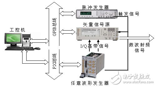
Figure 2. Hardware connection to the instrument
3.1.1 Arbitrary Waveform Generator The arbitrary waveform generator outputs baseband or intermediate frequency analog I/Q signals through digital storage and D/A conversion. Through software control, it simulates the function of a baseband analog signal generation module, enabling the following features: 1. Playback of pulse waveforms to generate single pulses or sequences. 2. Adjustable pulse width and internal waveform parameters such as frequency or bandwidth. 3. Software-configurable pulse width and resampling rate. 3.1.2 Vector Signal Source The vector signal source inputs I/Q signals and performs quadrature modulation and up-conversion. It allows remote control to adjust the following: 1. The center frequency and output power of the radar signal. 2. Amplitude and phase balance between the I/Q channels. 3.1.3 Pulse Generator The pulse generator provides trigger pulses for radar pulse modulation and sets the pulse repetition frequency (PRF), ensuring coherence and synchronization among modules. The key components in the system are the arbitrary waveform generator and the vector signal source. Major manufacturers offer corresponding products. For verification, we selected Agilent’s N6030A arbitrary waveform generator [2], E8267D vector signal source [3], and the 81110A pulse generator [4]. The 81110A and E8267D are connected via GPIB, while the N6030A uses a PXI bus. The industrial computer runs the virtual instrument software and communicates with the instruments through these buses to enable remote control. 3.2 Virtual Instrument Software Design The system software is structured as shown in Figure 3, adopting a modular design to support future upgrades and expansions. The instrument driver includes all necessary control functions and parameters for the instrument. The instrument control module extracts the required functions and parameters from the driver to meet user needs.
Figure 3. Block diagram of the system software
3.2.1 VEE Graphical Development Environment Virtual instrument development environments include common tools like VC++, VB, MATLAB, and specialized ones such as NI LabVIEW and Agilent VEE. In this project, Agilent VEE [5] was chosen due to its object-oriented programming approach, making it ideal for system simulation and instrumentation control. Key features include graphical programming using data flow diagrams, high efficiency, extensive instrument I/O drivers for VXI, GPIB, PXI, and serial interfaces, and compatibility with C/C++ and MATLAB. 3.2.2 Driver-Based Instrument Control Module Design An instrument driver is a collection of control functions and parameters that enable the operation of the instrument. It acts as a bridge between software and hardware. The virtual instrument software is built upon these drivers [6]. By receiving user input from the interface, the system can realize rich signal configuration and complete automated tasks. Calling the driver’s interface functions [7][8][9] allows the design of a system that meets all functional requirements.Fiber Cutter Tool,Fiber Cleaver Kit,Auto Return Cleaver,Single-mode fiber cleaver
Guangdong Tumtec Communication Technology Co., Ltd , https://www.gdtumtec.com