introduction
A permanent magnet synchronous motor having a trapezoidal back EMF is conventionally referred to as a DC brushless motor. The torque control of a brushless DC motor requires rotor position information to achieve effective stator current control. Moreover, for the speed control, the speed signal is also needed. The position sensor is the basis of the vector control of the brushless DC motor. However, the presence of the position sensor also brings many defects and inconveniences to the application of the brushless DC motor: First, the position sensor Will increase the size and cost of the motor; secondly, the connection of a large number of position sensors will reduce the reliability of the motor operation, even the most widely used Hall sensor, there is a certain degree of magnetic insensitive areas; again, in some bad The working environment, for example, in a sealed air conditioner compressor, due to the strong corrosiveness of the refrigerant, the conventional position sensor cannot be used at all; finally, the installation accuracy of the sensor also affects the running performance of the motor, increasing the process difficulty of the production.
Position sensorless control technology is an important direction in the research of brushless DC motors (BLDCM) in the past 30 years. The research status of BLDCM position sensorless control at home and abroad is discussed. The basic principles, implementation approaches, application scenarios, advantages and disadvantages of several conventional methods with many applications and researches are introduced, and they are comprehensively analyzed and compared. No position sensor control is the control that is performed without a mechanical position sensor. At this time, the rotor position signal as the inverter switching commutation timing signal is still indispensable, but it is no longer provided by the position sensor, but should be replaced by a new position signal detection measure, that is, to improve the circuit. And the complexity of control to reduce the complexity of the motor structure.
At present, the core of BLDCM position sensorless control research is to construct a rotor position signal detection circuit, which indirectly obtains a reliable rotor position signal from both hardware and software, thereby triggering the conduction of the corresponding power device and driving the motor. So far, among the many position signal detection methods, there are many applications and researches such as stator inductance method, speed-independent position function method, back EMF method, fundamental wave potential commutation method and state observer method.
1 Rotor position detection scheme based on back EMF
Brushless DC Motor (BLDCM) has the advantages of no reversing spark, reliable operation, convenient maintenance and simple structure, so it has been widely used in many occasions. However, conventional BLDCM requires an additional position sensor to control the rotor position, which has many adverse effects on its application. BLDCM's position sensorless control has been a hot research topic at home and abroad for nearly 30 years [1]. At present, for the position sensorless control of BLDCM, different control theories and implementation methods have been proposed for different performance requirements and applications, such as stator inductance method, speed independent position function method, back EMF method, fundamental wave. Potential commutation method, state observer method, etc. Based on a brief discussion of the current research status of BLDCM position sensorless control, this paper introduces in detail the basic principles, implementation approaches, applications, advantages and disadvantages of several types of methods that are currently applied and studied.
When the motor speed is greater than zero, there are only two positions where the opposite potential is zero in each electrical cycle. These positions can be distinguished from the slope of the back EMF through the zero crossing as shown in Figure 1. Each segment corresponds to 60 in the electrical cycle. ° interval. The commutation occurs at the boundary of each segment, and there is a 30° offset between the zero-potential zero-crossing point and the position that needs to be commutated, which needs to be compensated.
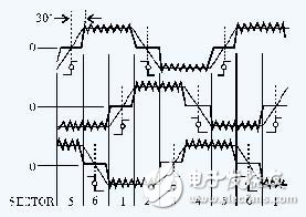
Figure 1 back EMF zero crossing
Only two phases are energized at any one time, and the current flowing through the two phases is reversed. Figure 2 shows the W phase for the back EMF detection. When a forward current (defined as a current flowing to the center point of the star connection) flows through the U phase, and a negative phase current flows through the V phase, the set 1 action corresponds to the interval 6Q and 1Q in FIG. Assuming that the two ends of the energized phase are always symmetrically connected to the two terminals of the DC power supply, the voltage at the center point of the star connection is always 1/2 VDC, regardless of the polarity of the voltage applied to the two energized phase windings. .
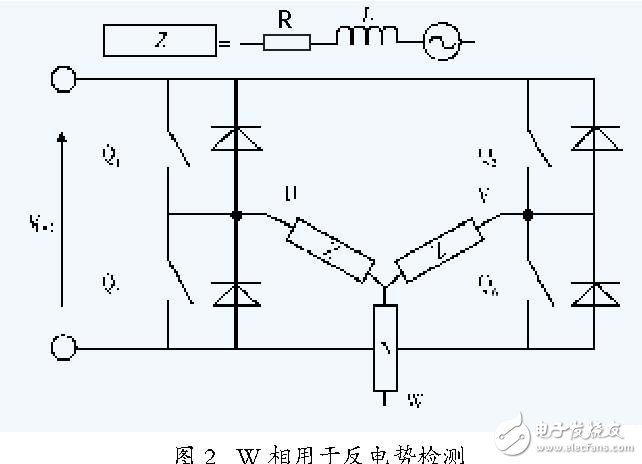
The above method is easily realized by hardware, that is, the three-phase terminal voltage and the VDC are separately sampled by the voltage dividing circuit, and the sampled value is sent to the comparison port of the comparator, and the obtained zero-crossing point is the time of 1/2 VDC. Use a useful opposite potential to measure the time of 60° (ie, between the two back EMF zero crossings).
2DSP control scheme system implementation
2.1 Introduction to TMS320LF240x chip
The TMS320LF240x family of DSPs is designed by TI to meet a wide range of digital motor control (DMC) applications. The chip features a high-performance 16-bit fixed-point DSP core with an improved Harvard bus architecture, a dedicated hardware multiplier, pipelined operation, and 30 MIPS of processing power. Most instructions can be executed in a single cycle. TMS320LF240x can realize the replacement of analog devices with software, complete complex control algorithms, easily modify control strategies, and correct control parameters to meet the requirements of real-time control of sensorless DC brushless motor control systems.
2.2 DSP control system hardware implementation
The DSP system consists of peripheral circuits such as TMS320LF2407A and emulation port (JTAG). DSP has 32K words of FlashROM inside, but for the convenience of debugging (programs in FlashROM can not set breakpoints, and need special download program), plus program RAM, when the program is debugged many times, it can be written when mature and reliable. The internal FlashROM can be executed from the internal FlashROM by setting the corresponding jumper. The DSP has 544 words of dual-port RAM (DARAM), all configured into the data space, and the frequently accessed variables in the program are allocated to this part of the dual-port RAM to improve the processing speed. The DSP also has 2K words of single-port RAM (SARAM) configured into the data space, which is also used to store temporary variables.
3 is a DSP-based DC brushless motor control system designed according to the aforementioned control principle. The system is mainly composed of a DC brushless motor, a power converter circuit, a motor rotor position detecting circuit, various protection circuits, and a digital controller with a TMS320LF240x as a core, wherein the power converter circuit is composed of a rectifying and filtering circuit and an inverter circuit. (IPM power module) and corresponding protection circuit.
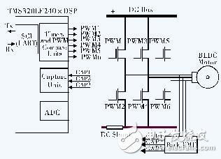
Figure 3 DSP control system
The IPM module in the inverter circuit integrates various protection functions such as overvoltage protection, undervoltage protection, and overcurrent protection. When the protection threshold is reached, the IPM module outputs a low level signal through the FO pin, and This low level signal is sent to the PDPINTx pin of the DSP to trigger the power drive protection interrupt. All PWM output pins are set to a high impedance state to turn off the drive signal and protect the circuit.
The rotor position detecting circuit is realized by the 1/2 voltage sampling method, and the three-phase terminal voltage and the DC bus voltage of the motor are separately sampled, and the sampling result is sent to the comparator for comparison, thereby obtaining the zero-crossing time, and the result is sent. Into the capture port of the DSP.
2.3 DSP control system software design
The control system adopts a control structure of speed and current double closed loop. Due to the high-speed DSP for motor control, whether it is the design of the speed loop, the realization of the current loop, the processing of various feedback signals and the generation of PWM control signals, digital signal processing technology is adopted, and the hardware circuit is realized by software. The function is to complete the real-time control of the DC brushless motor.
The software design of the control system mainly includes two parts: DSP initialization program and motor control program. The DSP initialization program mainly completes the system clock setting, the definition of the interrupt vector, the initialization of the I/O port, the setting of the control register and the initialization of each function module. The motor control program is mainly responsible for the start control of the motor and the double closed loop control of the speed current. , system monitoring and fault handling, etc., so the motor control program includes the start subroutine, current and position detection interrupt service subroutine, speed control subroutine, current control subroutine, PWM modulation subroutine, and system monitoring and fault handling subroutine.
The detection of various feedback signals is a prerequisite for the formation of double closed loop control. The detection of the position signal and the current signal are respectively implemented by the position detection interrupt service program and the current detection interrupt service program, and the detection of the rotation speed is indirectly obtained by software calculation. In order to improve the dynamic performance and steady state accuracy of the system. A schematic diagram of its control loop is shown in Figure 4.
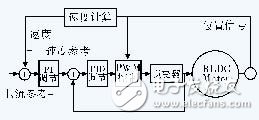
Figure 4 Current and speed control loop
The PWM modulation subroutine generates a PWM modulated signal through an event manager (EV) based on the detected rotor position signal and current signal. The general mode timer count mode is set to the continuous up/down counting mode by the bit pattern in the timer control register TxCON to generate a symmetric PWM waveform.
2.4 motor start-up plan
Since the DC brushless motor is difficult to correctly detect the back EMF signal during stationary and low speed operation, it is necessary to solve the problem that the motor is started at a standstill. In the past, there were various starting methods, but some had to add complicated starting circuits, and some had to be closely related to the characteristics of the motor, which was difficult to implement and low in reliability.
The system adopts the three-stage method to realize the motor starting simply by using software, and divides the starting process of the motor into three stages: pre-positioning, forced operation and synchronous switching. When the motor is stationary, the initial position of the rotor is unknown. It is necessary to apply a short-current current to the set two-phase armature winding to stabilize the rotor pole on the axis of the combined magnetic field of the two-phase winding, as the initial position of the rotor pole ( Pre-positioning). Then, according to the correct spatial phase relationship between the rotor poles, the corresponding power devices are turned on, and the mode is switched at a fixed time. During this time, the back electromotive amplitude is small, and zero-crossing detection is not suitable.
3 experimental results
The above control scheme is applied to the DC inverter air conditioner compressor system for experimental verification. The pole number of the motor is 2, the PWM carrier frequency is set to 5 kHz, the maximum output power is 2 kW, and the speed regulation range is 15 to 110 Hz. The experiment proves that the system starts smoothly, the speed control system has good real-time performance and good control performance. Figure 5 is the waveform of the three-phase voltage of the brushless DC motor, Figure 6 is the waveform of the three-phase current of the brushless DC motor. It can be seen from the waveform diagram that the output waveform has a higher quality, indicating the control strategy adopted by the system. And the feasibility and practicality of the algorithm.
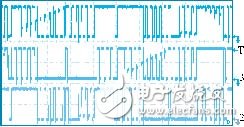
Figure 5 three-phase voltage waveform
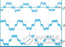
Figure 6 three-phase current waveform
4 Conclusion
The brushless DC motor has the advantages of high efficiency, high power density, high power factor, small size and high control precision, and its application range is very wide. The control technology of DC brushless motor is transitioning from the traditional closed-loop PID control with position sensor to the intelligent control without position sensor. The performance of speed range, torque ripple and system robustness are constantly improving.
Based on the powerful real-time computing power of TMS320LF240x and the rich integrated components on the chip, the control scheme of DSP-based sensorless DC brushless motor is designed, and the software and hardware structure of the control system are given. The control system has good control performance and speed regulation performance, and can obtain better dynamic characteristics and higher steady state accuracy, high operating efficiency, strong anti-interference ability, and high practical application value.
Tubular Motors for Roller Blind, Venetian Blind, etc.
Tubular Motors
Home Automation Control Motors,Multiple Limits Setting Motors,Quiet Tubular Drive,Tubular Motors
GUANGDONG A-OK TECHNOLOGY GRAND DEVELOPMENT CO.,LTD. , https://www.a-okmotor.com