With the continuous improvement of the power supply quality of power equipment and the power supply for special occasions and special geographical environments, the contact power transmission mode cannot meet the actual needs. In recent years, research on wireless charging technology has been increasing.
The wireless charging system emits electromagnetic wave energy, which also emits energy when there is no charging device on the transmitter, causing energy waste and radiation pollution. When a metal foreign object is placed on the transmitter, the electromagnetic wave heats it, and the device burns down, and a fire occurs. Therefore, the wireless charging system needs to have the function of recognizing the target of the power receiving end, and charging is performed when the correct target is placed on the transmitter.
Commonly used identification methods are: 1) magnetic activation, a magnet on the power receiving end, transmitting energy when the transmitting end senses the magnetic force; 2) enhancing the circuit safety through radio frequency identification (RFID); 3) data transmission on the induction coil Using the power transmission in the original secondary coil, including the data code transmission, this method is the safest and most difficult to complete, because the induction coil has high-energy power transmission, and also contains the interference of system noise and load current change. How to effectively transmit data codes is a big problem. Therefore, based on the primary voltage sampling circuit, a low frequency identification circuit is designed.
1 QI wireless charging communication standard
Under the Wireless Charging Alliance (WPC) standard, the power consumption of wireless transmission is only 0 to 5W. Systems that meet this standard range use inductive coupling between two planar coils to transfer power from the power transmitter to the power receiver. The distance between the primary and secondary coils is typically 5 mm, and the output voltage regulation is handled by a global digital control loop where the power receiver communicates with the power transmitter and generates power. This communication is a one-way communication from a power receiver to a power transmitter by backscatter modulation. In backscatter modulation, the power receiver adjusts the load, thereby changing the current consumption of the power transmitter. These current changes are monitored and demodulated into the information needed to work together on two devices.
Communication protocols include analog, digital acoustic ping (ping), identification, configuration, and power transmission. The typical startup sequence that occurs when a power receiver is placed on a power transmitter is as follows:
1) The analog ping from the power transmitter detects the presence of the object.
2) The digital ping from the power transmitter is an extended version of the analog ping and gives the power receiver time to reply with a signal strength packet. If the information strength packet is valid, the power transmitter will keep the coil energized and proceed to the next step.
3) During the identification and configuration phase, the power receiver sends some data packets, identifies them, and provides configuration and setup information to the power transmitter.
4) During the power transmission phase, the power receiver sends a control error packet to the power transmitter to increase or decrease the power. During normal operation, control error packets are sent every 250 ms, and every 32 ms during large signal changes. In addition, during normal operation, the power transmitter sends a power packet every 5 s.
5) In order to terminate the power transmission, the power receiver sends a "terminate charging" message or does not communicate within 1.25s, causing the power transmitter to enter a low power state.
2 The influence of the coupling coefficient of the primary and secondary coils on the primary LC voltage
Obtained by the RLC series resonant circuit
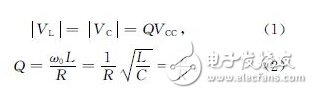
When there is an excessive air gap between the primary side sensing circuit and the secondary side sensing circuit structure, not only the energy receiving rate of the secondary side coil is deteriorated, but also when the secondary side circuit and the primary side circuit are far apart, the secondary side circuit reflection resistance becomes small. The Q value increases. It can be known from the RLC series resonant circuit that the inductor voltage is Q times the input voltage when resonance occurs. When the secondary side sensing circuit structure is far away from the primary side circuit, the Q value increases and the inductor voltage increases, so it can be detected by detecting the inductor voltage value. Determine whether the secondary side sensing structure is far from the primary side sensing circuit.
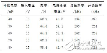
In addition to the air gap affecting the coupling coefficient of the primary and secondary coils, the size of the compensation capacitor also affects the coupling factor. The relationship between the compensation capacitor and the circuit coupling coefficient is shown in Table 1. When the compensation capacitance of the secondary circuit is changed, the resonance frequency also changes, and the coupling coefficient of the primary and secondary coils of the circuit also changes, and the efficiency of the circuit also changes accordingly. When the resonant frequency is close to the switching frequency, the coupling coefficient of the primary and secondary coils is large, the circuit efficiency is high, and the peak voltage of the inductor is small. When the circuit only has the secondary compensation capacitance changed, the magnitude of the peak voltage of the inductor reflects the change of the compensation capacitance of the secondary circuit.
Table 1 Relationship between compensation capacitance and circuit coupling coefficient
The object placed on the power transmitter may be an object with a high coupling coefficient, such as a metal coil, a wireless charging receiving module, or the like, or an object with a low coupling coefficient. For an object with a low coupling coefficient, it is not necessary to identify it because the charging efficiency of the wireless charger is low, the primary current is large, the LC circuit voltage is high, and the circuit switches after detecting a continuous high voltage state for a certain period of time. The tube is turned off and enters the standby state. For objects with a high coupling coefficient, they must be identified to prevent mischarging.
More wireless charging technology analysis / application case / market analysis, actually in the [Wireless Charging Technology Application Salon], registration stamp this!
Laminated Wood Pressure Ring is an indispensable insulation material in the power industry and transformer manufacturing.
The Laminated Wood Ring is one of the most basic in all of ring making, however it is also the most versatile. Once the blanks are made, creating a laminated wood ring is no different than making a solid wood ring.
Laminated Wood Pressure Ring
Laminated Wood Ring,Transformer Pressure Ring,Densified Wood Pressure Ring,Densified Transformer Laminated Wood Ring
Yingkou Dongyuan Electrical Insulation Board Co.,Ltd , https://www.dy-insulation.com