In analog/digital conversion, it is desirable to be able to pass down digital data with a minimum of wires. An analog/digital converter that outputs serial data can sometimes be used, which is certainly one way to solve this problem. But the solution itself has problems that need to be addressed. Analog/digital converters that can output serial data are often subject to the internal structure of a conventional serial bus, and the transmission speed is limited. Since such serial buses often perform single-ended signal transmission, electromagnetic interference is easily generated, which affects the stability of adjacent circuits. Common mode noise generated by adjacent circuits can also affect the stability of the serial bus, causing bit errors in data transmission.
This article refers to the address: http://
One way to overcome these problems is to use a low voltage differential signaling (LVDS) data bus. Figure 1 is a block diagram of one of the analog/digital converters with LVDS output signals to drive an ASIC or deserializer.
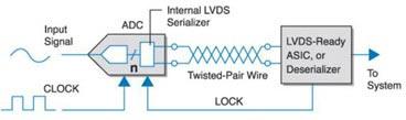
Figure 1: Block diagram
The analog/digital converter in the figure outputs a serial data stream in accordance with the LVDS signal format. The receiver then recovers the n-bit output using an application specific integrated circuit or deserializer that supports LVDS.
When power is turned on, the analog/digital converter and receiver enter a two-step startup process. This boot process is a process that ensures that different phase-locked loops within each chip can be synchronized. First, the receiver locks itself based on the pulse frequency provided by the oscillator. The phase-locked loop of the analog/digital converter is self-locking according to CLKIN. Then, the analog/digital converter outputs a column of data. The arrangement of the columns is called SYNC mode. The arrangement mode is as follows: any number of "1"s must have the same number of "0"s and counted according to the data output speed. The phase-locked loop in the receiver is locked in this SYNC mode and the "LOCK" signal is sent back to the analog/digital converter to inform the analog/digital converter that the receiver is locked and ready to receive any incoming data. The output data consists of three parts: the value is always the "start bit" of "1", the data of n bits, and the "termination bit" whose value is always "0". Figure 2 shows the general flow of data transfer.
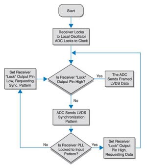
Figure 2: Process
So this frame is made up of n+2 bits of data, and the data stream frequency is (n+2) x fsample. The phase-locked loop of the receiver can receive data continuously as long as it is always locked. If the phase-locked loop slips out of the locked range, the LOCK line is set to a low state and the analog/digital converter again receives a request to provide a synchronous mode of operation.
The output driver of the analog/digital converter provides a constant current source that drives a twisted pair of 100W terminals, a stripline on a printed circuit, or a microstrip line. Figure 3 shows two terminal circuits typically placed near the receiver.
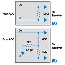
Figure 3: Typical terminal circuit
Figure 3 A is a simple terminal configuration. The line termination of the analog/digital converter is provided with resistors to help reduce any possible reflections. This resistor is also the load required for the constant current source current to produce an output signal. Figure 3B is another simple terminal configuration that uses common mode resistors as needed to reduce common mode on the cable. This method is less useful. As long as the differential signal format is used, the number of wires between the analog/digital converter and the deserializer can be minimized and the resulting magnetic field is tightly confined to the vicinity of the transmission line. This will reduce the electromagnetic interference of these lines, so as not to affect the adjacent circuits.
Application:
The electric cable tray system are widely used for:
1.railway bridge cables laying
2.highway bridge cables laying
3.petrochemical engineering cables laying
4.post and telecommunication cables laying
5.computer cables laying
Tray Type Corrosion Resistance Cable Tray
Stainless Steel Cable Tray,High Corrosion Resistant Cable Tray,Corrosion Resistance Cable Tray,Steel Ventilated Perforated Cable Tray
Jiangsu Loncin Electric Equipment Co.,Ltd , https://www.loncincabletray.com