Airbags play a key role in automotive assisted restraint systems (SRS). At present, the installation of airbags in passenger cars has become a standard. Everyone knows that airbags and seat belts can reduce the chances of the head and upper body of the car hitting the components inside the car when the car collides. They also reduce the risk of injury by distributing the impact force more evenly.
This article refers to the address: http://
But now, many people have realized that the auxiliary restraint system that can bring people safety can also endanger the safety of people in the car. Therefore, when developing a safety system, the various characteristics of the system must be fully considered to ensure that the required level of safety is achieved. In order to solve this problem, Infineon has developed a wide range of airbag trigger chips to help the system achieve automatic fault protection.
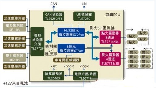
Figure 1: Schematic diagram of the ECU for the airbag.
The automotive airbag system market in Asia is expected to continue to grow, mainly due to the growth of the Chinese market. In the next five years, the market will grow by 25%.
In addition, South Korea's cars exported to Europe and the United States are equipped with more and more airbags, mainly because of the new safety regulations implemented in Europe and the United States. At present, South Korea's passenger cars have been equipped with 100% front airbags, and the increase in head airbags is expected to reach 44% by 2013.
The current positive airbag installation rate in the Chinese market is only 62%, so we expect the field to grow rapidly. In addition, as China's vehicle exports continue to grow, safety issues are getting more and more attention, so we expect side and head airbags to continue to grow in the next four years.
At present, with the implementation of new European and American regulations, the airbag system is expected to become more complete. Equipment manufacturers will face price pressures and need to address the challenges of balancing costs, innovation and reliability.
Related research shows that the current front airbag with an average selling price of $105 is expected to reduce costs by 15% after four years. The industry believes that reliable applications are the most important issue for automotive airbag systems, so this article will explore how to balance safety factors and system costs under poor execution conditions, such as leakage and low pressure.
In the past 30 years, the number of vehicles on the roads in Europe has increased by a factor of two, but the roads have only doubled. With the increasing traffic volume, Hyundai has presented an increasingly high level of safety and comfort for drivers and passengers.
Electronic technology and other chemical and mechanical technologies play an important role in improving vehicle safety and comfort. GPS systems, auto mirrors, automatic lights, power seats, electronic jets and hundreds of other functions are now an integral part of the car. But in addition to comfort, users also want to buy cars with higher security for themselves and their families.
Therefore, the security system is beginning to work. Currently, automobiles provide active and passive safety systems such as ABS, ESC, ASR, airbags, and pedestrian protection. In the future, the market is expected to continue to grow as the road is still far from 100% safe.
The new security system uses separate components to provide the required functionality, but in recent years, all systems have been integrated. At present, most RCUs (Security Control Units) are composed of an MCU (Master Control Unit), a communication interface, a power supply, a sensor interface, and a blasting circuit. This article covers the blasting circuit portion of the RCU. The safety of the airbag system and the relevant safety features of the application IC are discussed below.
Airbag safety
The development of a safety system must take into account the various characteristics of the system to ensure that the required level of safety is achieved. From a system perspective, the airbag controller must have two safety features: 1. Trigger in an accident condition; 2. Prevent accidental triggering.
Both of these characteristics must comply with the specific requirements of the relevant standard (ie IEC 61508) to ensure that the corresponding level of safety is achieved.
The safety standards of the safety system propose the concept of 'automatic fail-safety'. When a safety system fails, it should be designed to ensure that the failure does not damage adjacent systems or cause injury to personnel.
At first glance, one might think that the first feature is more important than the second feature. However, it is not. When the safety system detects an accident, if the trigger of the airbag cannot be completed due to some kind of failure, it will cause casualties. However, most owners still want to never need to trigger the airbag. On the other hand, after the RCU is installed in the car, from the car test period to the end of the use period, the airbag may be accidentally triggered at any time. If this happens, it can cause harm to the personnel involved (factory workers, car drivers or garage technicians).
On the whole, it should be ensured that the correct triggering of the airbag is achieved in the event of an accident, and efforts must be made to prevent accidental triggering of the airbag.
In order to enable everyone to better understand the airbag system and how to implement fault protection, it is necessary to introduce the implementation of the entire system.
Typically, the car satellite sensor interface acquires and analyzes the data sent by an external sensor (acceleration or pressure sensor). These sensors are distributed in the front end of the car, in the door or on the B-pillar depending on the function or type (front-end impact acceleration sensor, side-impact pressure sensor or side-impact acceleration sensor).
In the event of a collision, the absolute acceleration or pressure experienced by the sensor is greatly increased, causing the main microcontroller to know that a collision has occurred. At this point, the main microcontroller must decide whether to trigger the airbag based on the sensor's data, the onboard sensor's data, the position of the seat, and other parameters.
If it is decided to trigger the airbag, the main microcontroller will send an instruction to the blast interface. At the same time, the backup system (usually a spare 8-bit microcontroller) must also make decisions based on more basic data (ie, only onboard sensor data), allowing the designated hardware line to allow the blasting IC to trigger the airbag.
Triggering is accomplished by passing current through a squib (usually between 1.2A and 1.75A). The squib is here a resistor with a resistance of only a few ohms, so to save energy you must control the current. If the current flows through the squib for a certain period of time (usually 0.5ms to 2ms), the airbag will complete the trigger.
From generating sensor information, sending sensor information, analyzing all parameters, making decisions, transmitting decisions to the trigger IC, and finally ensuring that current passes through the squib only when needed, it must be reliable throughout this process Automatic fail-safe performance.
The analysis of the last two steps of the process of triggering the airbag will be carried out below.
Trigger IC security features
Infineon's existing trigger ICs feature a variety of features that ensure fail-safe functionality. These include:
1. CrosSave
2. Leak detection
3. Start the software and hardware to trigger
4. Resistance measurement
5. Switch test
6. High Side Power Supply (HSS) Diagnostics
7. Onboard voltage measurement
Among the above features, the former is designed to prevent accidental triggering, and the rest is used to ensure that the trigger is completed when needed. All of these features are discussed below.
CrosSave
In order to achieve fail-safe function in the event of a 'production failure' (defective wafer, ESD damage, etc.), the airbag system needs to be redundant or versatile. Each squib is equipped with two switches (see Figure 2). These two switches ensure that the current flows into the squib only under specified conditions.
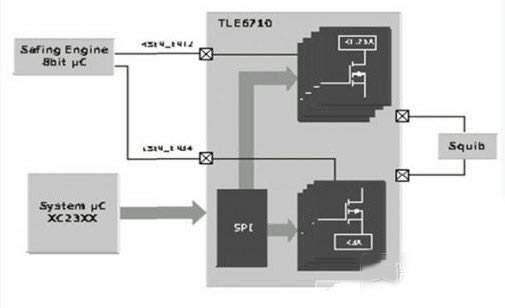
Figure 2: A simplified block diagram of an airbag driven wafer.
This feature can be achieved by using a single IC to integrate the high side (HS) and low side (LS) switches; using two identical ICs, but separating the high side switch from the low side switch through the PCB design (Cross-coupling); or two different chips can be integrated into one package (CrosSaveTM) using two different technologies.
When using a single IC, it can be dangerous if the chip fails. Since both switches are integrated on one wafer, the fail-safe function cannot be realized.
The second and the second methods separate the two switches. In the event of a fault, only one switch will be damaged and the fail-safe function can still be achieved. Which method is more secure requires further discussion.
CrosSave (see Figure 3) offers the advantages of a single package that saves board space and reduces design difficulty compared to other solutions, while always ensuring the system's fail-safe features.
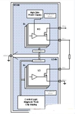
Figure 3: The discrete wafer concept of CrosSave.
On the one hand, cross-coupling uses redundancy to achieve fail-safe function. Redundant systems are less protected against common cause failures (CCF). On the other hand, CrosSave uses a diversity strategy that is better for CCF protection but has a higher coupling factor.
In summary, these two solutions provide more secure performance than single-chip systems.
Start hardware and software for triggering
The feature of preventing accidental triggering requires multiple external software instructions and multiple hardware lines must be in a predefined state before triggering.
The MCU must independently turn on two switches (high side switch and low side switch) using two different SPI commands. Therefore, even if a communication failure occurs and the SPI command is misinterpreted as a blast command, a second command is required to successfully blast.
For Infineon's TLE77xx series of explosion-proof ICs, the previous extra command UNLOCK can be used for explosion. Otherwise, the switch will be turned on and the current limit will be set to approximately 40 mA (diagnostic current limit), which is insufficient to ignite the squib.
As mentioned above, the hardware circuit must also reach a predefined voltage in order to perform a blast. This feature is different for products from different manufacturers. The TLE77xx blast IC series features four hardware lines: HSENQ, LSEN, FLENH and FLENL. Usually the first two are connected to the MCU and the other two are connected to the alternate security engine (ie 8-bit microcontroller).
HSENQ and LSEN turn on the high side switch and the low side switch even when executed under diagnostic current limit conditions. These lines must be connected to the MCU for the purpose of the switch test described below.
On the other hand, FLENH and FLENL also cause the blast current (1.2A..1.75A) to flow through the high side switch and the low side switch. Therefore, only when the MCU and the safety engine agree that a collision accident has occurred, the blasting current can be obtained from the accumulator to trigger the airbag.
Leak detection
In order to ensure that the explosion occurs only under specified conditions, a leak check must be performed. Leakage measurements prevent explosions when a switch is opened for testing (see Section 4.5). Since the squib is usually located at the front or side of the car and the RCU is located under the center console, a longer harness is required, which is likely to be a source of leakage.
Leaks are typically tested in the feed and return paths of the squib and are detected at these locations and at the ground and battery terminals.
Resistance measurement
The squib may cause aging throughout the life cycle, resulting in failure to complete the trigger in the event of a collision, so it is necessary to periodically measure the resistance to ensure that the squib is in normal working condition. If the resistance value is outside the safe range, the squib is turned off, the warning light is on, and the driver is alerted until the car is repaired. The resistance is measured using a small current (diagnostic current).
The resistance value is usually obtained using the analog output 燃 of the blasting IC.
High Side Power Supply Test (HSS)
For systems with high side switches, it is often necessary to generate high voltage to drive the MOSFET gate. The high voltage of the TLE77xx blast IC series is provided by the accumulator. If the voltage of the accumulator is too low, the high voltage is supplied by an external capacitor (high side supply capacitor CHSS).
These ICs are able to monitor the state of external capacitors and prevent triggers from being completed due to capacitive faults when necessary.
To complete this test, you need to use the current source of the TLE77xx blast IC series to get current from the high-side supply capacitor. Since the current is constant, it is only necessary to measure the voltage twice at a fixed interval to obtain the capacitance value. Therefore, when the capacitor is excessively aged, it is necessary to alert the driver to replace the capacitor.
Switch test
Of course, in order to ensure the correct completion of the trigger, the blasting IC must perform a self-test on the switch. These switches prevent accidental triggering (possible), but on the other hand, when a crash occurs, both switches (high side switch and low side switch) need to be activated to complete the trigger. If one of them fails, the RCU cannot perform one of these functions.
The switch test method is similar to the leak measurement. Since the leakage current flowing to the battery occurs when the high-side switch is turned on, the leakage current flowing to the ground line occurs when the low-side switch is turned on. Therefore, the leakage measurement should be performed first, and then one of the switches should be turned on.
According to the operation described in Section 4.3, not only the software command is required, but also the hardware input line needs to be set to an appropriate value from the MCU side.
Onboard voltage measurement
Finally, ICs often have the ability to measure all voltages on a board. The low voltage indicates a fault (the MCU and other ICs cannot be executed normally, the trigger cannot be completed, etc.). In order to avoid these faults, most of the trigger ICs used by the RCU can measure external voltages, including VCC5, VBOOST and VBAT, and even measure the internal voltage of the IC to detect possible faults.
Measurement results are usually output using IC analog-to-digital and MCU analog-to-digital converters.
Summary of this article
This article explores the safety issues associated with airbag systems. Describe the safety features of the system by describing how the safety system avoids casualties under fault conditions. All of these features make the airbag system safer and protect the car from fatal injuries in a car accident.
SMT Cylinder And Sensor will be for sales
Smt Cylinder and sensor includes serveral brands,original and new, stable function, in stock
Juki Sensor
Juki Laser Sensor
Juki Smt Sensor
Laser Sensor
Juki Cylinder
Juki Square Cylinder
Juki Air Cylinder
Cylinder Square
Square Cylinder
SMT Cylinder And Sensor
Air Cylinder,Smt Cylinder,Smt Sensor,Original Cylinder
Shenzhen Srisung Technology Co.,Limited , https://www.sr-smt.com