LEDs are solid-state semiconductor devices that convert electricity directly into light. LEDs have many advantages such as small size, low power consumption, long service life, high brightness, low heat, environmental protection, and durability. This makes LED light sources have great advantages in the face of traditional light sources and is widely used. The surface area of ​​the LED chip is small, the current density is high during operation, and it is often required to combine a plurality of LEDs for illumination, and the LED density is large, resulting in high heat generation density of the chip. The increase in junction temperature results in a decrease in light output, which accelerates the chip and shortens device life. The light-emitting diode drifts toward the long-wave direction as the junction temperature rises. If you want to take into account the adverse effects of color drift in practical applications, thermal design also limits the maximum junction temperature. Due to the continuous increase of the input power of LED chips, the packaging technology of these power LEDs has put forward higher requirements. Today's heat dissipation has become a key factor constraining the development of high-power LEDs. Especially for the application to the car headlights, because the structural design is in line with the aesthetic limitations of the model, the heat dissipation environment of the LED is further deteriorated, so the heat dissipation problem of the LED car lamp needs special consideration.
2 LED heat dissipation research
2. 1 LED lamp heat transfer process
For an LED luminaire, heat is first generated from the LED chip and then transmitted through heat transfer, convection, and radiation. In view of the actual structure of the luminaire, heat conduction is the most important heat transfer method. Therefore, when designing how to improve the heat dissipation performance of the LED luminaire, the designer mainly achieves the purpose by changing the heat conduction capability of each link of the LED luminaire system.
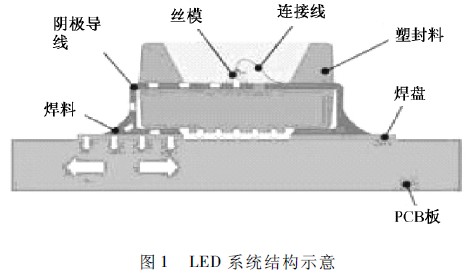
Figure 1 shows the structure of two typical LED systems [1]. It can be seen that the thermal performance of the LED luminaire system is directly determined by the LED-circuit board-air thermal resistance, and three channels are involved in this channel. Main links: (1) The size of the thermal resistance of the LED device directly affects whether the heat generated by the chip can be exported to the bracket or the Heat Sink. It is necessary to improve the heat dissipation performance of the LED from the LED package structure, packaging material and manufacturing process; 2) The thermal resistance from the LED to the board is often determined by the material of the board, the spacing between the LEDs, the distribution of the resistors, and the way the LEDs are connected to the board; (3) if the board-to-air thermal resistance is too large Even if heat is transferred from the chip to the metal circuit board, the heat of the focus will cause the temperature of the circuit board to rise sharply, resulting in excessive temperature, increasing the possibility of LED failure, resulting in increased LED light decay and shortened life. Therefore, we improve the heat dissipation capability of LED lamps from these three aspects, thus controlling the LED junction temperature within a certain range.
2. 2 LED system heat dissipation
2. 2. 1 LED internal heat dissipation
For the internal heat dissipation of the LED device itself, since the heat generated by the PN junction is mostly transmitted to the outside through the substrate, the adhesive and the heat sink, the improvement of the internal heat dissipation involves the chip substrate, the adhesive, the heat sink, and the like. The selection of materials and the design of the manufacturing process and packaging structure.
The first thing that can be thought of and is the simplest is to increase the thermal conductivity of the internal substrate, adhesive, heat sink, and increase the heat transfer area, which can reduce the thermal resistance. However, due to space constraints, the increase of heat transfer area is limited, and the selection of internal materials is also affected by various factors such as material properties, price, and process level.
For the pasting material, it is very important to ensure the thermal conductivity of the device by selecting the appropriate chip substrate bonding material and ensuring that the bonding thickness is as small as possible in the mass production process. Usually, three materials such as thermal conductive glue, conductive silver paste and tin paste are used for pasting. The thermal conductivity of the thermal conductive adhesive is poor, and the conductive silver paste has both good thermal conductivity and good adhesion strength. However, since the silver paste heats up while raising the height and contains toxic metals such as lead, it is not the best choice for the bonding material. Compared with the former two, the thermal conductivity of the conductive solder paste is the best among the three materials, and the electrical conductivity is also excellent.
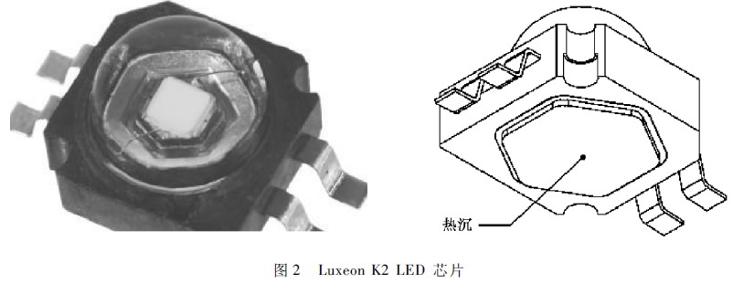
Lumids's Luxeon K2 power LED, introduced in 2006, uses a copper heat sink to enhance heat dissipation for good heat dissipation, as shown in Figure 2.
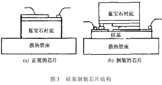
In recent years, researchers have proposed a so-called silicon-based flip chip package structure. Conventional LEDs use a formal structure with a layer of epoxy resin on top and sapphire as a substrate. Due to the poor thermal conductivity of epoxy resin, sapphire is a poor conductor of heat, and heat can only be dissipated by the pins under the chip. Therefore, the problem of heat dissipation is difficult to occur on both the upper and lower sides, which affects the performance and reliability of the device. In 2001, LumiLeds developed the AlGalnN power flip chip structure. The LED chip is flip-chip connected to the silicon substrate. This heat does not have to pass through the sapphire substrate of the chip, but directly to the silicon or ceramic substrate with higher thermal conductivity, and then to the metal base. Since the active heating region is closer to the heat sink, the internal heat sinking heat can be reduced. Resistance. However, the thermal resistance is proportional to the thickness of the heat sink. Due to the mechanical strength and thermal conductivity of the silicon wafer, it is difficult to further reduce the thermal resistance of the internal heat sink by thinning the silicon wafer, which further restricts the heat transfer performance. 2], see Figure 3.
2. 2. 2 The effect of PCB selection on heat dissipation
In the process of transferring heat inside the LED to the external environment, it is necessary to pass through the substrate, so improving the thermal conductivity of the PCB is crucial for the heat dissipation of the entire LED system. At the same time, the PCB also plays a role in the electrical connection and physical support of the LED chip, so the design of the substrate must consider both electrical and heat transfer performance.
The substrate material of high-power LEDs must have high electrical insulation resistance, high stability, high thermal conductivity, thermal expansion coefficient similar to that of the chip, and flatness and certain strength. A small number of metals or alloys can meet the requirements of high thermal conductivity and low expansion coefficient. In order to ensure electrical insulation, it is necessary to coat a polymer film or deposit a ceramic film.
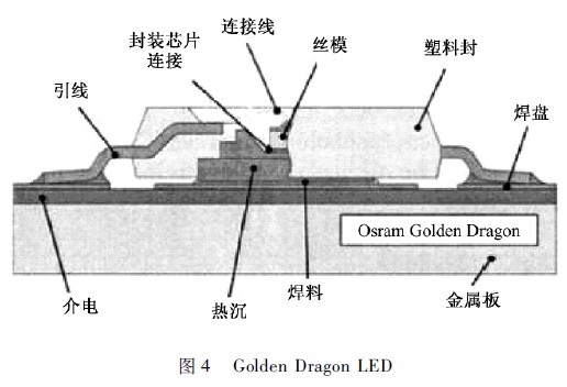
The metal circuit board (MCPCB) structure commonly used by major LED manufacturers now uses a metal such as aluminum with excellent thermal conductivity to package the chip on a PCB board covered with a few millimeters thick copper electrode, or to package the chip in a metal. The sandwiched PCB board is then packaged onto the heat sink to solve the thermal problem. UOE's Norlux series of LEDs assembles the packaged product on a metal core PCB with an aluminum interlayer. The PCB is used for the electrode connection of the LED device, and the aluminum interlayer acts as a heat sink. Although the structure can obtain good heat dissipation characteristics and greatly increase the input power of the LED, the PCB in the interlayer is a poor conductor of heat, which hinders the conduction of heat. OSRAM's GoldenDragon series LED system is shown in Figure 4. Its structural feature is that the heat sink is in direct contact with the metal circuit board and has good heat dissipation performance; the chip is soldered on the copper alloy thermal diffusion layer by infrared or reflow soldering, and the thermal diffusion layer is soldered on the aluminum core PCB board.
The comminuted reduction of the co-firing shrinkage to about 0.1% by the low-temperature sintering of the multilayered ceramics on the copper-molybdenum-copper (CuMoCu) metal. , far below the 12.7% to 15% of the standard LTCC and HTCC processes. The molybdenum-copper composite has a thermal expansion coefficient similar to that of the chip, and the ceramic layer has a high dielectric property, and the LED chip can be directly mounted on the metal plate layer. Excellent thermal conductivity allows Lamina Ceramics to arrange multiple LED illuminating points at high densities, resulting in exceptionally high light in a small area [3].
2. 2. 3 Heat dissipation on the PCB side
The heat of the LED chip is transmitted to the PCB through the internal path. If the PCB is directly transmitted to the air side, the heat transfer performance will be poor. The easiest way is to add a heat sink on the PCB side to expand the heat sink surface, and then use a fan to force air convection. This can improve the heat dissipation of the LED system. This method can only be applied to LED systems with lower heat flux density, which is not suitable for high heat flux density. In addition, in recent years, some of the following cooling technologies have been developed for LED systems:
(1) Some newly designed heat sinks can further improve heat dissipation. For example, some manufacturers install a heat sink with a pin rib on the back of the LED module to solve the heat dissipation problem of the small LED module. At the same time, the piezoelectric fan can further improve the heat dissipation capability of the LED system.
(2) It has also been proposed to use a micro heat pipe to achieve heat dissipation. The heat pipe utilizes phase change to enhance heat transfer, has good heat transfer performance and light weight, and can transport heat over a long distance, and is suitable for dissipating heat from a narrow space; and the introduction of the micro heat pipe can conform to a narrow space of the lamp, thereby Improve the efficiency of heat transfer. However, due to the limitation of the structure of the lamp, the form of the loop heat pipe must be used, which has the disadvantage that the cost is too high.
(3) Synthetic micro-injection technology. This technique uses diaphragm vibration to change the surrounding gas pressure to form a jet. When the vibration frequency of the diaphragm is between 100 and 200 Hz, the maximum injection speed of the main flow zone can reach about 30 m / s. When the synthetic micro-spraying operation is zero, the static mass flow rate is zero, and the cycle can be completed by itself, and no additional circulating parts are needed. In terms of air cooling, the heat dissipation efficiency of the synthetic micro-jet is 2 to 3 times that of a conventional fan, and the energy consumption is less than half of the fan. The synthetic micro-spray cooling system is complex and costly, and is currently not suitable for LED automotive headlamps.
(4) Microchannel heat dissipation technology. In the 1980s, American scholars Tuckerman and Pease reported a microchannel heat sink with a groove width and a wall thickness of 50 μm. Although microchannel technology has been proposed very early, the lack of small micropumps has become an important factor limiting its development. Goodson et al. used an electroosmotic drive cycle to implement an electroosmotic pump. The electroosmotic pump has no moving parts and low energy consumption. It has been confirmed that when the heat flow is 200W, the microchannel heat dissipation method driven by the electroosmotic pump can reduce the temperature rise by 20 degrees, while the pump consumes less than 1 W. At present, microchannel heat dissipation technology has not been commercialized.
(5) Thermoelectric cooling technology. Thermoelectric refrigeration differs from several of the above-described heat dissipation technologies in that it can locally create surfaces that are cooler than ambient temperatures. Thermoelectric refrigeration mainly uses the Peltier effect. However, its cooling efficiency is only 10% of the Carnot cycle efficiency, which is still lower than other refrigeration methods.
In recent years, researchers have proposed many other forms of cooling, which are briefly described as follows:
In 2005, Ma et al. proposed a channel cooling module for LED arrays. They connect a flat plate made of MMC (Metal Metric Composite) or Si material under the LED array, and then micro-machining technology is formed in the flat plate to form a micro-channel, and the liquid flows through the channel to achieve the purpose of heat dissipation. In order to enhance heat transfer, they further arrange ribs in the channel to improve heat dissipation.
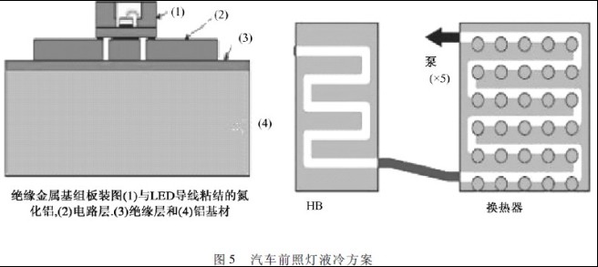
. In 2006, Lai et al. reported on LED automotive headlamp liquid cooling solutions. The liquid cooling system is designed for a vehicle light model consisting of multiple LEDs. The liquid cooling system consists of a pump, a cold plate in which the LED device is placed, a water storage tank, a heat exchanger, and a flexible hose. The working medium is water containing an additive. After the working medium flows out of the pump, it passes through the cold plate, passes through the radiator, and finally flows back to the pump. The cold plate is connected to the heat source of the IMS structure, as shown in Figure 5. At the same time, the article points out that air convection cooling and passive liquid cooling are not suitable for the heat dissipation of LED lamps. The active cooling solution achieves better cooling and allows the LED chip to operate at normal temperatures. However, this system is more complicated, and the reliability of the liquid circuit in the moving environment makes this solution not currently used in the automotive lamp market [4].
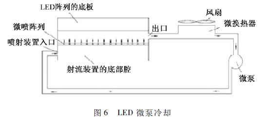
In 2006, Sheng Liu et al. solved the heat dissipation problem of LEDs by installing a micropump system on the heat sink, as shown in Figure 6. In a closed system, water enters the small groove of the LED under the action of the micro pump to absorb heat, and then returns to a small water container to dissipate heat through the fan. The micro-pump structure has good refrigeration performance, but if the internal interface has a large thermal resistance, its thermal conductivity is greatly impaired, and its structure is also complicated [5].
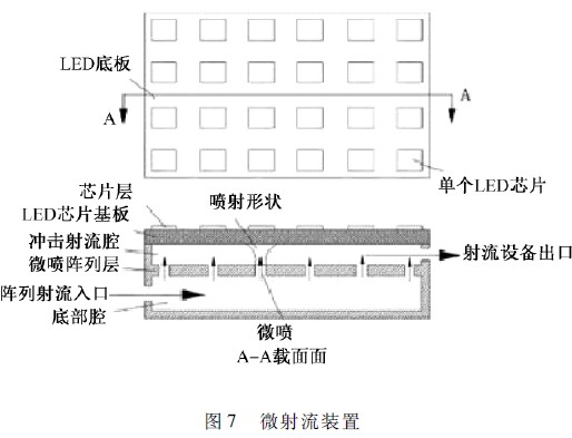
The microfluidic device is shown in Figure 7.
The device is currently used in demonstration products for high power LEDs, but not in the field of automotive lights.
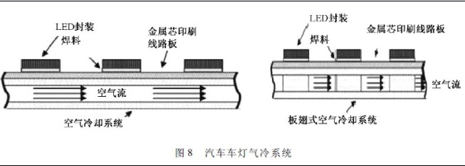
In 2008, Moo Whan Shin et al. used an air-cooling system to dissipate heat from car lights. The unit uses air-cooled MCPCB boards for heat dissipation, both finned and non-finned. Because of the source of the airflow and the outside world, the heat dissipation effect is highly dependent on the speed of the car [6] (Figure 8).
to sum up
In summary, in the future, LED system cooling can be studied from the following aspects to improve the heat dissipation performance of high-power LEDs [1]:
(1) How much heat is generated by the LED depends on the internal quantum effect. In the growth process of GaN materials, the material structure should be improved, and the growth parameters should be optimized to obtain high-quality epitaxial wafers, thereby improving the quantum efficiency in the device, fundamentally reducing heat generation, and accelerating heat conduction from the chip junction to the epitaxial layer. ;
(2) Select aluminum-based metal core printed circuit board (MCPCB), ceramic, DBC, composite metal substrate and other substrates with good thermal conductivity to accelerate heat dissipation from the epitaxial layer to the heat dissipation substrate. By optimizing the thermal design of the MCPCB board or directly bonding the ceramic to the metal substrate to form a metal-based low-temperature sintered ceramic (LTCC-M) substrate, a substrate having good thermal conductivity and a small thermal expansion coefficient can be obtained;
(3) In order to allow the heat on the substrate to diffuse more quickly into the surrounding environment, metal materials such as aluminum and copper are usually used as heat sinks, and forced cooling such as fans and loop heat pipes is added. At the same time, other effective new cooling methods can be considered;
(4) For high-power LED devices, the total thermal resistance is the sum of the thermal resistance of several heat sinks on the PN junction to the external environment, including the internal heat sink resistance of the LED itself, and the internal heat sink to the PCB board. The thermal resistance of the thermal paste, the thermal resistance of the thermal paste between the PCB and the external heat sink, the thermal resistance of the external heat sink, etc., each heat sink in the heat transfer loop will cause some hindrance to heat transfer. Therefore, the number of internal heat sinks is reduced, and the necessary interface electrode heat sink and insulating layer are directly fabricated on the metal heat sink by a thin film process, which can greatly reduce the total heat resistance.
Die casting is a metal casting process, which is characterized by the use of mold cavity to apply high pressure to melted metal. Molds are usually made of higher strength alloys, a process somewhat similar to injection molding. The cost of casting equipment and mould is high, so it is easy to manufacture die-casting parts, so the single cost is very low, so it is especially suitable for manufacturing a large number of small and medium-sized castings. Therefore, die casting is one of the most widely used casting processes.
Die Casting Process,Odm Aluminium Die Casting,Suction Pump Die Casting Part,Gravity Aluminium Die Casting
Dongguan Formal Precision Metal Parts Co,. Ltd , https://www.formalmetal.com