Board design is a critical and time-consuming task, and any problem requires engineers to examine the entire design on a network-by-component basis. It can be said that the design requirements of the board are as good as the chip design.
A typical board design flow consists of the following steps:
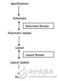
The first three steps take the most time because the schematic check is a manual process. Imagine a SoC board with 1000 or more connections. Manually checking each connection is a tedious task. In fact, it is almost impossible to check each connection, which can lead to problems with the final board, such as incorrect wiring, floating nodes, and so on.
The schematic capture phase generally faces the following types of problems:
â— Underscore error: such as APLLVDD and APLL_VDD
â— Case problem: such as VDDE and vdde
â— Misspelling
â— Signal short circuit problem
â— There are many more...
To avoid these errors, there should be a way to check the complete schematic in a matter of seconds. This method can be implemented with schematic simulation, which is rarely seen in the current board design flow. Schematic simulation allows you to see the final output at the desired node, so it automatically checks for all connection problems.
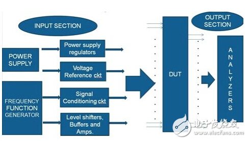
The following is explained by a project example. Consider a typical block diagram of a board:
In complex board designs, the number of connections can reach thousands, and very few changes are likely to waste a lot of time checking.
Schematic simulation not only saves design time, but also improves board quality and increases overall process efficiency.
A typical device under test (DUT) has the following signals:
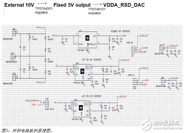
The device under test will have various signals after some pre-adjustment, and there are various modules, such as voltage regulators, op amps, etc., for signal adjustment. Consider an example of a power supply signal obtained by a voltage regulator:
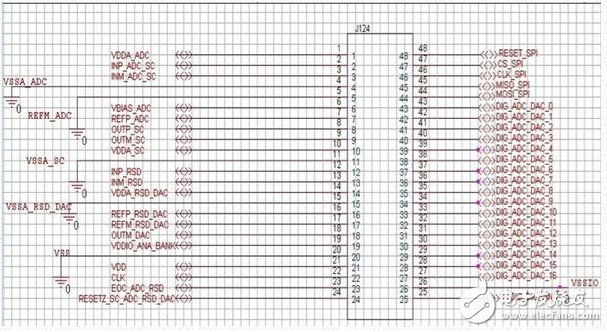
In order to verify the connection and perform an overall check, a schematic simulation was used. Schematic simulation consists of schematic creation, test platform creation, and simulation.
During the test platform creation process, an excitation signal is sent to the necessary input, and then the output is observed at the signal point of interest.
The above process can be implemented by connecting a probe to a node to be observed. The node voltage and waveform can indicate if there is an error in the schematic. All signal connections are automatically checked.
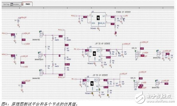
Let's take a look at a part of the above picture where the nodes and voltages detected are clearly visible:
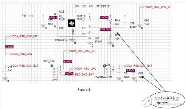
So with the help of simulation, we can directly observe the results and confirm that the schematic of the board is correct. In addition, a survey of design changes can be made by carefully adjusting the stimulus signal or component values. Schematic simulation can therefore save board design and inspectors a lot of time and increase the chances of design correctness.
PACSystems* RX7i Controller
• Pentium® CPUs for your every need, from Celeron 300Mhz to M Class 1.8Ghz • VME64 Backplane provides up to four times the bandwidth of existing Series 90*-70 systems • 10/100 Ethernet built into the CPU, with easy cabling RJ-45 dual ports connected through an auto-sensing switch - no need for additional switches or hubs rack to rack • Up to 64MB memory for fast execution, storage of the complete program with all documentation (including Excel, Word, PDF and DXF files) - all in one CPU • Object Oriented programming through IEC languages including C for fast executing, standards based applications • Integration of Control Memory Xchange, a high speed global memory over a fiber network - like having a networked drive everyone can see and share • High capacity power supplies (100W and 350W) to reduce the requirement for an external supply
PAC Systems RX7i Controller,Turbine Control System,RX7i 17 Slot Rack,Speedtronic Mark IV Turbine
Xiamen The Anaswers Trade Co,.LTD , https://www.answersplc.com