This example introduces an ozone sterilizer made of CD4069 six-gate digital integrated circuit. It has manual control and light control function. It can be used to make a disinfection cabinet or put it in a refrigerator as a deodorizer.
Circuit Operation Principle The ozone sterilizer circuit consists of a manual control/light control conversion circuit, a delay control circuit, an oscillator and a high voltage generator circuit, as shown in Figure 9-109.
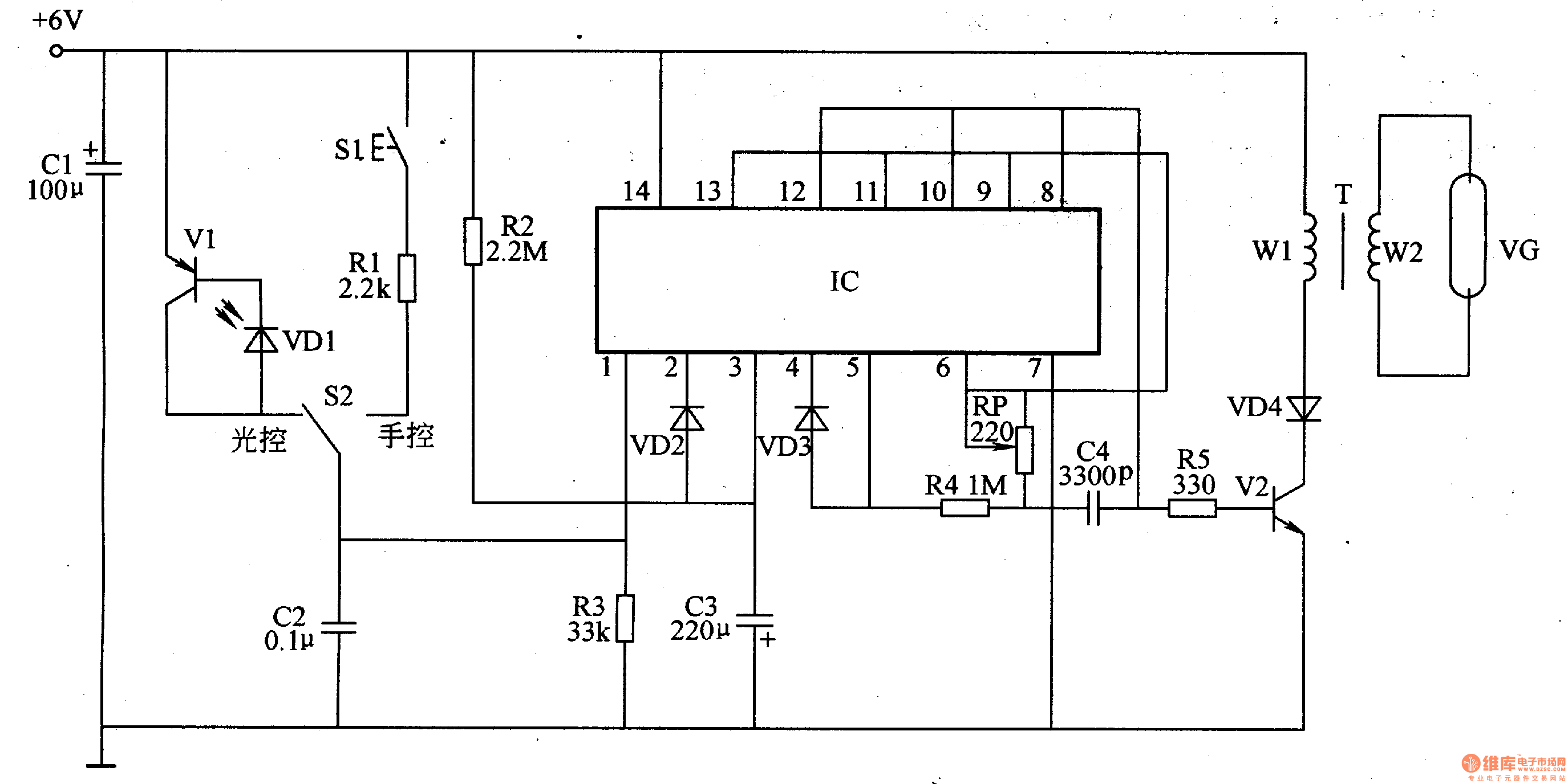
The manual control/light control conversion circuit is composed of a photodiode VD1, a transistor V1, a changeover switch S2, a manual control button S1, and a resistor R1.
The delay control circuit is composed of a six-gate integrated circuit IC, a resistor R3, capacitors C2 and C3, and diodes VD2 and VD3.
The oscillator circuit consists of an IC and resistors R2, R4, a potentiometer RP, and a capacitor C4.
The high voltage generator circuit is composed of a transistor V2, a resistor R5, a diode VD4, and a step-up transformer T.
When S2 is placed in the light control position, it can be used as a refrigerator to deodorize. When the refrigerator door is opened, the illumination inside the refrigerator lights up, VDl is illuminated by light and the internal resistance is reduced, then Vl is turned on, so that the IC's l, 4 and 5 feet become high, the oscillator starts working, from the IC The 8-pin output oscillates the pulse signal. After the pulse signal is amplified by V2 and boosted by the transformer T, a pulse high voltage is generated across the secondary winding of T, and ozone is generated through the discharge tube. After closing the refrigerator door, VDl is in a high-resistance state due to no light, Vl is cut off, IC's 1 pin becomes low level, 2 feet, 3 feet are high level, C3 starts charging, 6-12min after lC 4 The pin and pin 5 go low, and the oscillator and high voltage generator stop working.
When the S2 is placed in the manual position, it can be used for disinfection of dishes and the like. Press S1, IC's l, 4, and 5 feet go high, the oscillator and high voltage generator work, and the discharge tube produces ozone. After releasing S1, the oscillator and high voltage generator will automatically stop working after 6-12 minutes of delay.
Adjusting the resistance of the RP can change the operating frequency of the oscillator.
Component selection
Rl-R5 uses 1/4W carbon film resistor or metal film resistor.
The RP uses a small solid potentiometer or a variable resistor.
Both Cl and C3 use aluminum electrolytic capacitors with a withstand voltage of 16V; C2 uses polyester capacitors or monolithic capacitors; C4 uses high-frequency ceramic capacitors.
VDl selects 2CU or 2DU series of photodiodes; VD2 and VD3 select 1N4148 type silicon switch diodes; VD4 selects 1N4007 type silicon rectifier diodes.
Vl selects C8550 or S8550 silicon PNP transistor for use; V2 selects silicon NPN transistor of 3DmO5F or 2SCl031, 2N4240 and so on.
IC selects CD4069 six non-gate integrated circuit.
S1 selects the dynamic (normally open) type button; S2 selects the single pole and double position switch.
T is wound with an "E" core: the primary winding is wound with φ0.49mm enamelled wire around 3-5 turns, and the secondary winding is wound with φ0.18mm enameled wire around 900-1200 turns.
Circuit Operation Principle The ozone sterilizer circuit consists of a manual control/light control conversion circuit, a delay control circuit, an oscillator and a high voltage generator circuit, as shown in Figure 9-109.
The manual control/light control conversion circuit is composed of a photodiode VD1, a transistor V1, a changeover switch S2, a manual control button S1, and a resistor R1.
The delay control circuit is composed of a six-gate integrated circuit IC, a resistor R3, capacitors C2 and C3, and diodes VD2 and VD3.
The oscillator circuit consists of an IC and resistors R2, R4, a potentiometer RP, and a capacitor C4.
The high voltage generator circuit is composed of a transistor V2, a resistor R5, a diode VD4, and a step-up transformer T.
When S2 is placed in the light control position, it can be used as a refrigerator to deodorize. When the refrigerator door is opened, the illumination inside the refrigerator lights up, VDl is illuminated by light and the internal resistance is reduced, then Vl is turned on, so that the IC's l, 4 and 5 feet become high, the oscillator starts working, from the IC The 8-pin output oscillates the pulse signal. After the pulse signal is amplified by V2 and boosted by the transformer T, a pulse high voltage is generated across the secondary winding of T, and ozone is generated through the discharge tube. After closing the refrigerator door, VDl is in a high-resistance state due to no light, Vl is cut off, IC's 1 pin becomes low level, 2 feet, 3 feet are high level, C3 starts charging, 6-12min after lC 4 The pin and pin 5 go low, and the oscillator and high voltage generator stop working.
When the S2 is placed in the manual position, it can be used for disinfection of dishes and the like. Press S1, IC's l, 4, and 5 feet go high, the oscillator and high voltage generator work, and the discharge tube produces ozone. After releasing S1, the oscillator and high voltage generator will automatically stop working after 6-12 minutes of delay.
Adjusting the resistance of the RP can change the operating frequency of the oscillator.
Component selection
Rl-R5 uses 1/4W carbon film resistor or metal film resistor.
The RP uses a small solid potentiometer or a variable resistor.
Both Cl and C3 use aluminum electrolytic capacitors with a withstand voltage of 16V; C2 uses polyester capacitors or monolithic capacitors; C4 uses high-frequency ceramic capacitors.
VDl selects 2CU or 2DU series of photodiodes; VD2 and VD3 select 1N4148 type silicon switch diodes; VD4 selects 1N4007 type silicon rectifier diodes.
Vl selects C8550 or S8550 silicon PNP transistor for use; V2 selects silicon NPN transistor of 3DmO5F or 2SCl031, 2N4240 and so on.
IC selects CD4069 six non-gate integrated circuit.
S1 selects the dynamic (normally open) type button; S2 selects the single pole and double position switch.
T is wound with an "E" core: the primary winding is wound with φ0.49mm enamelled wire around 3-5 turns, and the secondary winding is wound with φ0.18mm enameled wire around 900-1200 turns.
Can be applied to all kinds of supermarkets, chain store POS ticket printing It can be used for catering, entertainment, automatic inquiry, automatic number picking and other bill printing Features: Adopt high-performance imported Thermal Printer core Simple and practical easy loading paper structure Optional Centronics parallel interface or RS-232 serial interface Speed up to 100mm/s Both parallel and serial interfaces Support nine kinds of barcode printing Support large print, center print Supports a variety of command systems and drivers
80Mm Thermal Printer,Thermal Inkjet Printer,Portable Thermal Printer,Thermal Sticker Printer
ShengXiaoBang(GZ) Material Union Technology Co.Ltd , https://www.sxbgz.com