Brand AVX TPSE226M035R0125 Low impedance tantalum capacitor AVX 22
Electronic scale crystal oscillator 3.2*2.5mm 3225 16M (16.000MHZ) 12PF 10PPM 20PPM 30PPM
One-piece inductor
Circuit Operation Principle The electronic weight loss instrument circuit consists of a power supply circuit, a multivibrator, a pulse width control circuit, a pulse group interval control circuit, an inverter circuit, an output control circuit, and a drive output circuit, as shown in Figure 9-36.
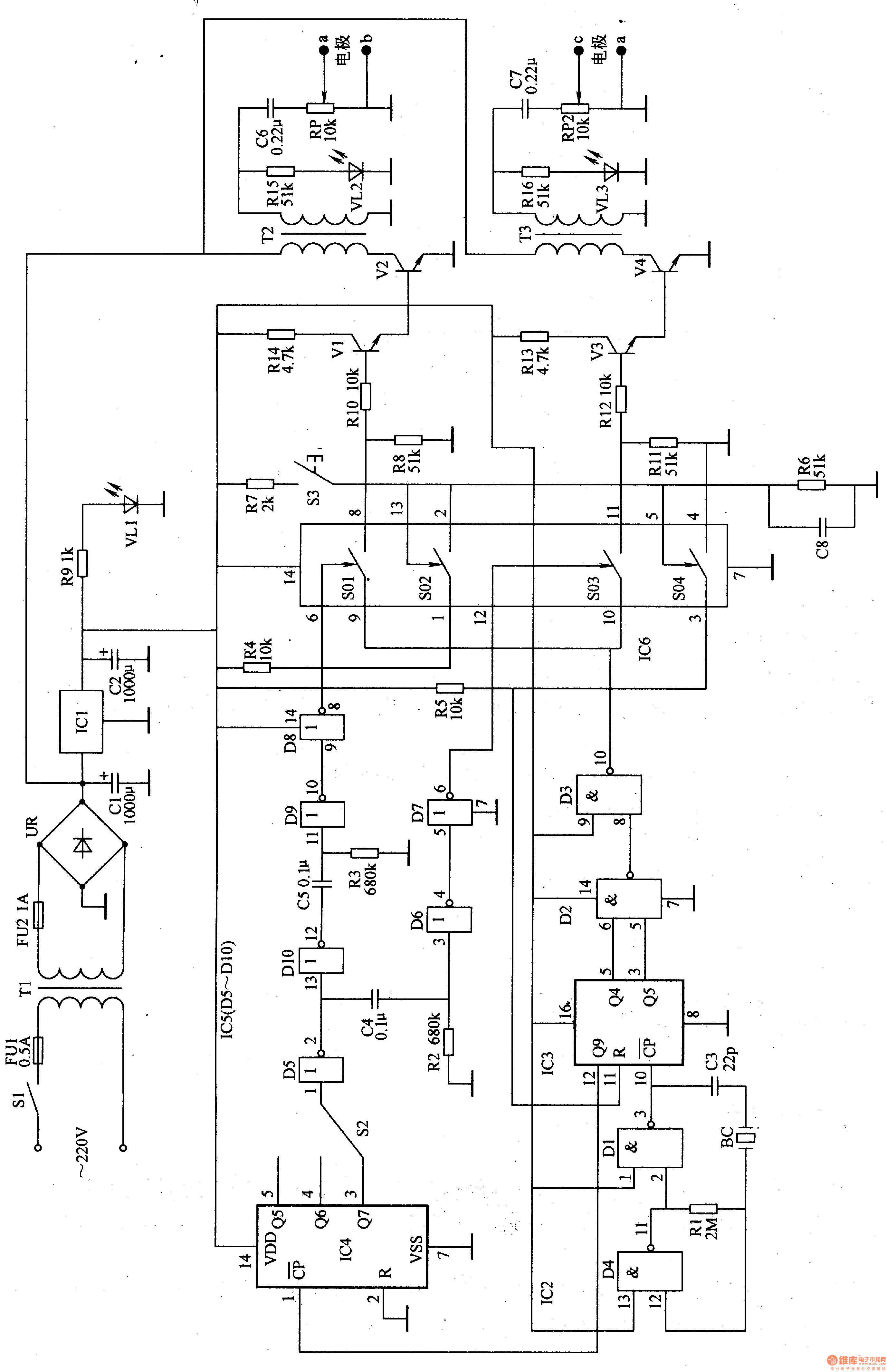
The power circuit is composed of fuses FU1, FU2, power switch Sl, power transformer Tl, rectifier bridge stack UR, filter capacitor Cl, C2, current limiting resistor R9, power indicating LED VLl and three-terminal integrated voltage regulator IC1.
The multivibrator is composed of two NAND gate circuits D1, D4 and a quartz crystal oscillator BC, a capacitor C3, and a resistor R1 inside the four-NAND gate integrated circuit IC2.
The pulse control circuit is composed of 12-bit binary counter/divider integrated circuit IC3 and two NAND gate circuits D2 and D3 inside 1C2.
The pulse group interval control circuit is composed of a 7-bit binary counter/divider integrated circuit IC4, a selection switch S2, and a non-gate circuit D5 inside the six-gate integrated circuit IC5.
The inverter circuit is composed of the non-gate circuit D6-D10 inside the lC5.
The output control circuit is composed of an analog switch integrated circuit IC6, a button S3, resistors R6, R7, and a capacitor C8.
The output driving circuit is composed of transistors V1-V4, pulse step-up transformers T2, T3, potentiometers RP1, RP2, capacitors C6, C7, resistors R15, R16, and light-emitting diodes VL2, VL3.
After the power switch S1 is turned on, the AC 220V voltage is stepped down by Tl, UR rectified, and Cl filtered to generate a 9V DC voltage. The voltage is directly supplied to the output driver circuit; the other channel is regulated to +5V by IC1 as the operating voltage of IC2-1C6. +5V also lights up VL1 after R9 current limit.
After the multivibrator oscillates, the low frequency oscillating signal is output from the 3 pin of IC2, and this signal is added to the 10th pin of lC3 in the pulse width control circuit for frequency division processing. The pulse signal after IC3 frequency division processing is divided into two ways: one is output from IC3's 3rd and 5th pins, and is processed into a narrow pulse signal through IC2's internal NAND gate circuit D2 and D3, and then added to IC6's 10 The foot; the male pulse signal is output from the 12-pin of the IC3, and after being divided by the IC4 in the pulse group interval control circuit, the pulse signals of different frequencies are respectively output from the 3rd, 4th, and 5th pins of the lC4. A pulse signal of a certain frequency is selected from the three signals outputted by the 3-5 pins of the 1C4 by the selection switch S2, and then two non-gate circuits are buffered and inverted by the IC5 to generate two pulses of opposite phases. The group interval control signals are added to pins 6 and 12 of IC6 respectively. The analog switches S01 and S03 inside IC6 are intermittently turned on and off under the control of the 8C and 6-pin pulse signals of 1C5. The two output drive circuits of the 8th and 11th pins of the lC6 operate under the control of the analog switches S01 and S03. When the analog switch S01 inside 1C6 is turned on, S03 is turned off, and the transistors V1 and VZ are turned on. V3 and V4 are turned off; when S01 is off, S03 is turned on, Vl and V2 are turned off, and V3 and V4 are turned on). The secondary sides of the pulse step-up transformers T2 and T3 alternately generate high-voltage pulse trains, and are applied to the parts of the human body that need to lose weight through the electrode sheets a, b, and c, and d.
S3 is the start button. Only when S3 is pressed, the analog switches S02 and S04 inside IC6 are turned on. When the 11 pin of IC3 goes low, the pulse width control circuit and the pulse group interval control circuit work, and the output drive circuit only has High voltage pulses are generated.
Component selection
Rl-R16 selects 1/4W carbon membrane resistor or metal membrane resistor for use.
Both RPl and RP2 use small synthetic carbon film potentiometers.
Cl uses aluminum electrolytic capacitors with a withstand voltage of 25V; C2 selects aluminum electrolytic capacitors with a withstand voltage of I6V; C3 uses ceramic capacitors; C4, C5 and C8 select monolithic capacitors or polyester capacitors; C6 and C7 select resistance Polyester capacitors or CBB capacitors with a pressure greater than 160V.
UR selects 2A, lOOV rectifier full bridge.
Both Vl and V3 use C805O silicon NPN transistors; V2 and V4 select 2SC2611 or D2611 silicon NPN transistors.
ICl selects LM7805 type three-terminal integrated voltage regulator; IC2 selects CD4011 type two-terminal input NAND gate integrated circuit; IC3 selects CD4040 type 12-bit binary count/divider integrated circuit; IC4 selects CD4024 type 7-bit binary count/minute Frequency IC; IC5 selects CD4069 type six non-gate integrated circuit; IC6 selects CD4066 type four bidirectional analog electronic switch integrated circuit.
VLl-VU selects high brightness LEDs of φ3mm or φ5mm.
S1 selects SA, 220V power switch; S2 selects small, single-pole three-position switch.
Tl selects 5W, the secondary voltage is 9V power transformer; T2 and T3 select lW, 9V power transformer (use T2 and T3 secondary winding to V2 and V4 respectively).
High Speed Bag Making Machine,High-Speed Continuous Roll Bag Making Machine,Automatic Roll Bag Making Machine,Compound One System Bag Machine
Dongguan Yuantong Technology Co., Ltd. , https://www.ytbagmachine.com