DFN1006 TP-RCLAMP3321P ESD Diode Low Capacitance
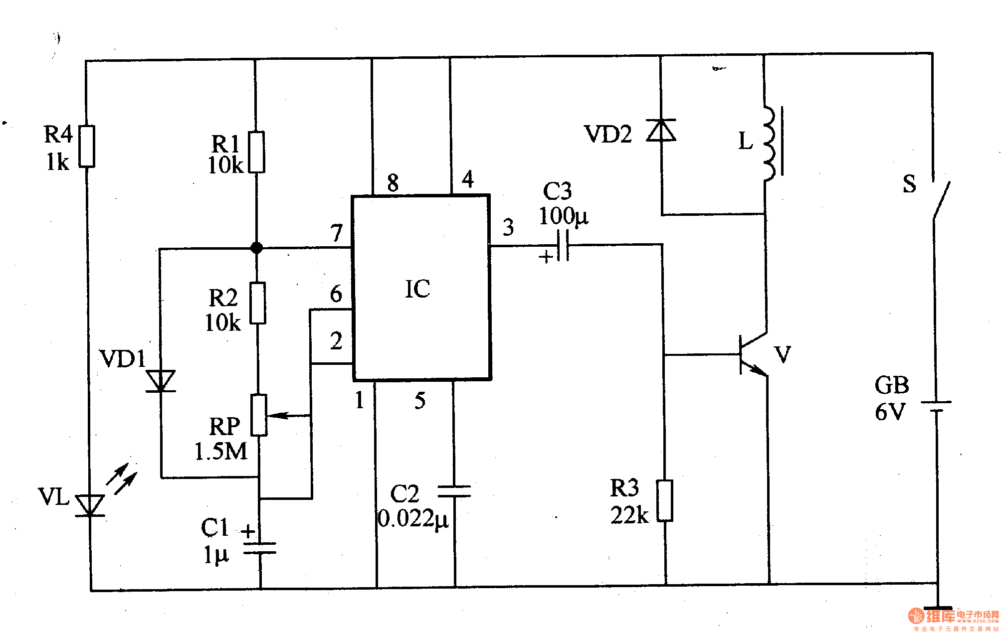
The ultra low frequency oscillator circuit is composed of a time base integrated circuit IC, resistors R1, R2, a potentiometer RP, capacitors C1, C2, and a diode VD1.
The magnetic pulse generating circuit is composed of a resistor R3, a transistor V diode VD2, and an electromagnetic coil L.
The power circuit is composed of a power switch S, a battery GB, a current limiting resistor R4, and a power indicating LED VL.
When the power switch S is turned on, the 6V DC voltage of the GB is supplied to the ultra-low frequency oscillator and the magnetic pulse generating circuit, and the VLA is also turned on after the R4 current limiting step-down.
The ultra-low frequency oscillator oscillates after power-on, and the ultra-low frequency oscillation signal whose frequency is adjustable is output from the 3 pin of the IC, so that V is intermittently turned on. When the IC 3 pin outputs a high level, V saturation turns on, L generates a magnetic field due to the current flowing; when the 3 pin of lC outputs a low level, V is turned off, "the stored energy is quickly vented through VD2. As V is intermittently turned on, L can generate a pulsed magnetic field.
Adjusting the resistance of the RP can change the oscillation frequency of the ultra-low frequency oscillator, that is, change the frequency of this pulse.
Component selection
Rl-R4 uses 1/4W carbon film resistor or metal film resistor.
The RP uses a small organic solid potentiometer.
Cl and C3 use aluminum electrolytic capacitors with a withstand voltage of 16V; C2 uses monolithic capacitors or polyester capacitors.
VDl selects 1N4148 type silicon switch diode for use; VD2 selects 1N4007 type silicon rectifier diode for use.
V selects 3DK4 type silicon NPN transistor for use.
lC selects NE555 type time base integrated circuit.
S selects a small single-pole switch with a contact current capacity greater than 2A.
GB selects 6V small capacity maintenance-free battery, and can also use small DC regulated power supply.
L is made by using an enamel wire of about φO.lmm around a magnetic bar of φOmmx3Omm for about 4,200 。.
Transparent Led Film Screen,Adhesive Transparent Led Display,Adhesive Led Transparent Film Screen,Transparent Led Display Film Screen
Guangdong Rayee Optoelectronic Technology Co.,Ltd. , https://www.rayeeled.com