introduction
A hydraulic braking energy regeneration system (HBRS) is used to transform bus power systems. The vehicle braking energy recovery and regeneration device composed of an electromagnetic clutch, a hydraulic pump motor and a hydraulic accumulator, and related mechanical devices and oil passages is connected in parallel with the bus power transmission device through a transfer box. The system converts the kinetic energy of the bus during braking into the hydraulic energy storage of the accumulator, and converts the hydraulic energy into the kinetic energy of the vehicle when the vehicle accelerates to start, so as to achieve the purpose of energy saving and emission reduction.
HBRS uses hydraulic accumulators as energy storage elements. Because the characteristics of the hydraulic accumulator's own energy storage determine the nonlinearity of the system's operating characteristics, the electronic control unit can be used to adjust the effective displacement of the hydraulic pump motor in real time to optimize the system's operating performance. The HBRS control system includes periodic tasks and an event-triggered task. The system can be designed using a time-triggered mode. This paper establishes a real-time analysis model for the HBRS control system, analyzes the characteristics of periodic tasks and triggered tasks, and designs a hybrid task scheduler based on the time-triggered mode.
1 System solution overview
In the hydraulic brake energy regeneration control system, the driver expresses the intention of accelerating or decelerating by manipulating the accelerator pedal and the brake pedal. In the hydraulic system, the opening and closing of the electromagnetic directional valve, the coupling / disengagement of the electromagnetic clutch and the adjustment of the effective displacement of the variable pump motor are all automatically completed by the centralized control of the electronic controller. The control system scheme is shown in Figure 1.
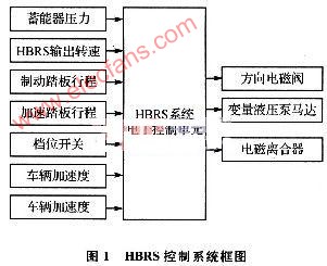
The electronic controller of the HBRS control system completes three major functions: status detection, effective displacement decision-making, and effective displacement execution logic control. The state detection module calculates the current vehicle speed, brake pedal stroke, accelerator pedal stroke, and accumulator pressure according to the sensor data, and differentiates according to the vehicle speed to obtain vehicle acceleration, and then transmits these state information to the effective displacement decision module. The effective displacement decision module judges the driver's operating intention based on the brake pedal switch, accelerator pedal switch, system enable switch and gear switch, thereby determining the system working mode (braking energy recovery mode, braking energy regeneration mode, braking energy Hold mode or forced pressure relief mode). The effective displacement execution logic control module queries the optimal effective displacement drive current matching table according to the vehicle speed, vehicle acceleration, brake pedal position or accelerator pedal position, obtains the target drive current parameter, and fine-tunes the drive current according to the vehicle acceleration. If the current system operating mode does not match the target operating mode, then issue a control command to drive the corresponding switching solenoid valve, so that the system enters the corresponding working mode, drive the electromagnetic clutch solenoid valve to realize the coupling or disconnection of the electromagnetic clutch; If the drive current does not match, the effective displacement execution logic control module adjusts the drive current to drive the hydraulic pump motor displacement adjustment mechanism to complete the drive of each solenoid valve in the system working mode and the control of the effective displacement adjustment current of the hydraulic pump motor.
2 Real-time system modeling
2.1 Division of functional modules
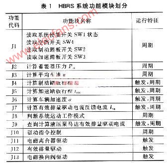
The functional module is the basic research object of the real-time system, and the related functional modules constitute a system task. In the hydraulic braking energy regeneration control system studied in this paper, there are 13 functional modules, as listed in Table 1. The periodic function modules in the table run periodically with respect to the time axis, and the trigger module only operates in the braking energy regeneration and braking energy recovery working modes.
2.2 Interconnection characteristics between functional modules
The interconnection characteristics of each functional module in the HBRS control system are shown in Figure 2. The arrows in the figure indicate the relationship between the functional modules (there are two types of timing relationship and resource sharing relationship), the direction of the arrow indicates the timing, and the circles and squares indicate the function Piece. The prerequisites of the circled function blocks are mutually related, and the prerequisites of the square function blocks are or relations. The hollow indicates that the subsequent operation of the function block has no branch, and the solid indicates that the function block has a branch. The execution of the subsequent function block is determined by the branch logic: I (x, y, z) is the relationship, x is the prerequisite, y is the follow-up task, and z is the shared resource name. ua is the vehicle speed, Iacc is the accelerator pedal stroke, lbra is the brake pedal stroke Pac is the accumulator pressure, a is the vehicle acceleration, and Ivg is the feedback current. C1 is the electromagnetic directional valve drive command, C2 is the electromagnetic clutch engagement / disengagement drive command, and C3 is the variable displacement motor effective displacement drive current command. This system uses pulse width modulation to control the regulation current.
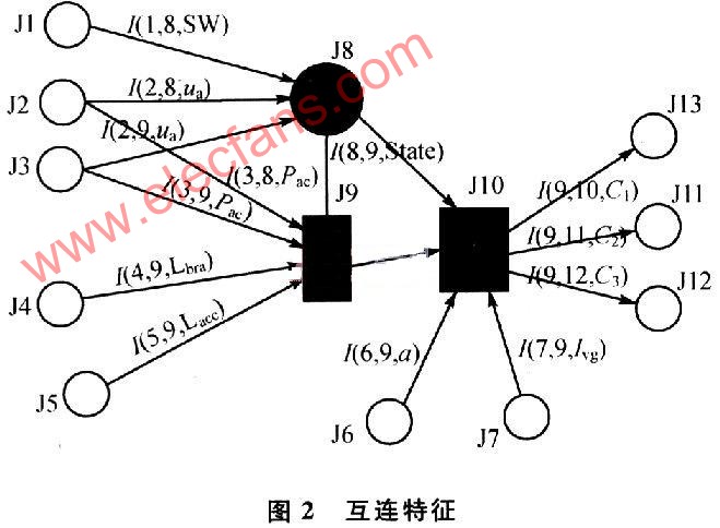
In this model, the prerequisite for the effective displacement decision module J8 to run is that J1 to J5 run first, that is, to obtain various switching states, vehicle speeds, and accumulator pressures. After logical judgment, the working mode of HBRS is decided. J8 has branches. When J8 judges that the system working mode State is the energy-maintaining working mode, J10 directly sends the default drive command without triggering J9. J10 controls the switching state of each electromagnetic directional valve, and controls the on / off state of the electromagnetic clutch. J9 needs to obtain the vehicle speed and brake pedal stroke in the braking energy recovery working mode, and query the control current corresponding to the optimal displacement. In the braking energy regeneration working mode, it needs to obtain the vehicle speed and accelerator pedal stroke to query the best and effective The control current corresponding to the displacement. J10 revises the control current value according to the current vehicle braking acceleration and the magnitude of the feedback current, and sends a drive command to the drive module. J9 and J10 are in different working modes and require different sensor signals or state variables. Therefore, a judgment program needs to be added to achieve the purpose of triggering different control programs in different working modes.
2.3 Task division
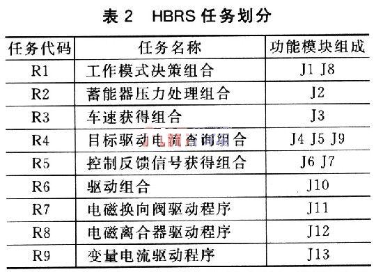
According to the principle of task division, I / O dependency, function cohesion, and task restraint, the 13 function modules are divided into 6 tasks, as listed in Table 2. Among the nine tasks, R1 ~ R6 are scheduled by the system control processor chip, and R7 ~ R9 are controlled by the microcontroller integrated peripherals. J10 and J11 are driven by the chip TLE6230GP, and J12 is implemented by the PCA and expansion chip 33486A of the control chip, and the PWM signal output is realized by the single-chip PCA module.
3 Scheduling algorithm design
When the HBRS enable switch is turned on, the system has four working modes: braking energy recovery mode, braking energy regeneration mode, braking energy holding mode and braking energy forced pressure relief mode. The control system makes logical judgment on which work mode the HBRS enters, so the task R1 work mode decision combination is a task that runs periodically. If it is judged that the system enters the braking energy pressure maintaining working mode or the forced pressure releasing working mode, the R6 drive combination is directly tasked; R6 issues a driving command to control the peripherals, and runs through tasks R7 and R8 to control the on-off of the electromagnetic directional valve The change of the oil circuit controls the coupling / disengagement of the electromagnetic clutch to realize the separation of the HBRS and the vehicle's original power transmission system; if R1 judges that the system enters the braking energy recovery working mode or the braking energy releasing working mode, the task R4 is triggered to query the target drive current , And trigger task R5 to calculate the vehicle acceleration and task R6 to calculate the feedback current value to provide to task R10 to correct the target drive current value; finally, through task R9 to achieve the adjustment of the effective displacement of the HBRS system.
The process of determining the required time-scale interval is: In order to reduce the overhead and power consumption to a minimum, the scheduler's time-scale interval should be set to the "maximum common factor" of the running interval of all tasks and meet the running time of all tasks All should be less than the scheduling time interval, to ensure that the scheduler can always call it when any task needs to run, and it is also required to avoid task jitter as much as possible.
Therefore, the tasks of the control system in different working modes all complete the detection and driving tasks within a deterministic time period, which simplifies the complexity of the system design and is more reliable and safer.
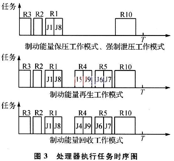
The timing of the control system processor performing tasks is shown in Figure 3.
4 Simulation
A control system is based on the use of Xinhualong C8051F005 minimum system board. First, the instantaneous characteristics of a single task running under the system are counted, a real-time system analysis model is established, a hybrid timing scheduling algorithm is implemented, and CPU utilization and task delay are counted for verification.
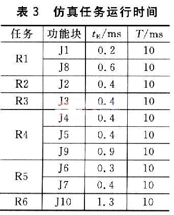
The instantaneous characteristic data of the control system are listed in Table 3. Among them, the task running period T is proposed according to the needs of the system performance, and it is feasible on the development platform. The maximum execution time tE is the number of times it is repeatedly run on the development platform to obtain the maximum value. result.
According to the hybrid scheduling algorithm, the timing simulation results of the 9-task and 4-processor real-time control system in each working mode are shown in Figure 3, and the simulation ignores the processor resources consumed by task context switching. According to Table 3, the maximum common divisor of the task is 10 ms, so the time axis is divided into time slices with a period of 10 ms.
Let the time scale interval be 1.5 ms, and the HBRS mixed timing scheduling sequence under the development platform is shown in Figure 4, in which the processor is in the dormant state during the blank period.
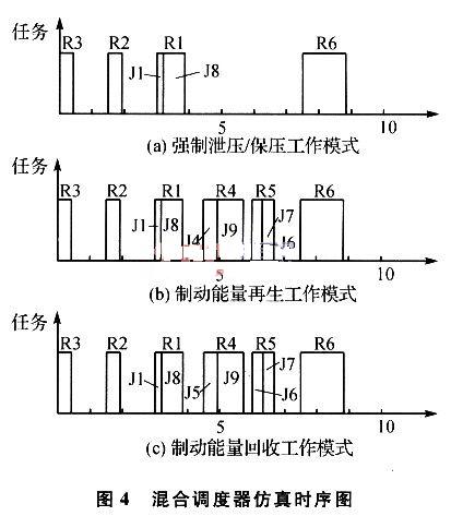
Figure 4 (a) illustrates the timing of the processor's task execution when the HBRS electronic control system is in forced pressure relief and hold pressure operation mode. At this time, the processor determines the working mode of the system through task R1 according to the vehicle working state information collected by tasks R3 and R2, and executes task R6 to issue a control command if it is a forced pressure relief or holding pressure working mode.
4 (b) and 4 (c) illustrate the timing of the tasks performed by the processor when the HBRS electronic control system is in the braking energy regeneration operating mode and the braking energy recovery operating mode. The difference between the two modes is that the sub-tasks triggered in task R4 are J4 and J5. Task R1 judges that the system works in the braking energy regeneration working mode, triggers task R4 to query and calculate the drive current value of the effective displacement of the hydraulic pump motor, and triggers task R5 to collect the vehicle's load status to correct the drive current value, and sends the HBRs to each system through task R6 Drive commands for solenoid directional valves, solenoid clutches, and hydraulic pump motors.
Conclusion
In this paper, the time-triggered mode is used to design the hybrid scheduler of the electronic control system of the hydraulic braking energy regeneration system, which realizes the basic functions of HBRS. Time-triggered mode scheduler can be conveniently designed through functional module division, task division and time series design. The electronic control system designed by time trigger mode has the characteristics of safety, low cost and simple procedure.
Automotive Connector,Copper Busbar,Hdmi Connector,Deutsch Connector
Dongguan Andu Electronic Co., Ltd. , https://www.idofuseholder.com