![]()
3528 white light
The filament in the bulb is triggered by a high-melting delay. When the tungsten alloy wire at the instant of turning on the light is wound into a spiral tube, the capacitor C can be regarded as a short circuit. The thyristor (thyristor, which is short for the thyristor rectifier element, is a four layer with three PN junctions). The structure of high-power semiconductor devices, also known as thyristors, has the characteristics of small size, relatively simple structure, strong function, etc. It is one of the more commonly used semiconductor devices. The device is widely used in various electronic devices and electronic products, and is widely used. For controllable rectification, inverter, frequency conversion, voltage regulation, non-contact switch, etc. Dimming lights, speed control fans, air conditioners, televisions, refrigerators, washing machines, cameras, stereos, sound and light in household appliances Circuits, timing controllers, toy devices, radio remote controls, video cameras, and industrial controls all use a large number of thyristor devices. The molybdenum wire bracket is then used to fix the glass SCR on the glass housing because there is no trigger voltage. The cold resistance of the filament is broken. After the AC current is rectified, the pass is very small, the thermal resistance is very large, the female D40W over-resistance R1 and the bulb form a loop, the bulb has a cold resistance of about 130 Ω, and the thermal resistance is up to be when the point A is positive and the B point is negative. 1.2k Ω. The thermal resistance value is about 1/10. The flow is determined by the A-D1-R1-D3-B- power supply. It flows through the lamp bulb-A at the moment of turning on the light. When the A point is negative, the B point is the positive wire. The current is very large. If the light is turned on instantaneously, the current is affected by the overvoltage surge between B-D2-Rl-D4-A-. Consider the bulb-power-B. Due to the current limit of R1, this inrush current is as high as the working effect so that the whole loop is not Will produce 20 times the current. At the same time, it greatly impacts the large inrush current. At this moment, the thermal shock generated by the bulb current causes the voltage across the filament to be approximately the part of the supply voltage (usually 1 / 2 of the filament and the lead wire, so the bulb illuminates at the junction of the blush frame) to form a high temperature color. At the same time, the alternating current is “hot spot†after rectification. Each time the light is turned on, the “hot spot†table charges all the capacitors through R2, and the tungsten molecules on the surface will evaporate some. The voltage across the capacitor C gradually rises, and the “hot spot†machine can be turned on after multiple turns of the light. The silicon-controlled SCR trigger voltage performance is greatly reduced. This is the main reason why the thyristor SCR is turned on at the moment of turning on the light, and the bulb between the R1 is easily burned. Short-circuit by thyristor SCR, AC current The circuit described below can effectively avoid the rectification and then burn the bulb through the thyristor and the bulb without turning on the lamp, which can form a loop, due to the purpose of the rectifier diode and its long service life.
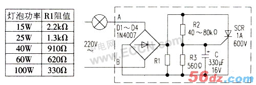
Circuit Introduction The circuit principle is shown in Figure 1. Bridge rectifier (bridge rectifier is bridged by multiple rectifier diodes, externally sealed with insulating plastics. High-power bridge rectifiers are encapsulated with metal shells outside the insulation to enhance heat dissipation. Bridge rectifiers have many varieties and performance. Excellent, high rectification efficiency, good stability, maximum rectified current from 0.5A to 50A, highest reverse peak voltage from 50V to 1000V.) The subsequent DC voltage is applied between the anode and cathode of the unidirectional thyristor SCR. Resistor R1 is the current limiting resistor of the bulb. The internal resistance of the resistors R2 and R3 and the capacitor C group SCR are small. Therefore, the supply voltage is almost all added to the bulb, and the bulb is normally illuminated.
As can be seen from the figure, the bulb and the life extension circuit are connected in series to the power supply, and the current will cause a voltage drop on the circuit. The voltage drop is determined by the forward voltage drop of the two rectifier diodes and the thyristor SCR turn-on voltage drop, with a total voltage drop of less than 2.5V. If the circuit consumes 1.36W when the circuit is connected to 100W, it can be seen that the power consumption is small and the power supply of the power supply is not increased. Only the power gained by the bulb drops slightly, apparently has little effect on the brightness of the bulb.
When the device is assembled and powered on. The bulb should be dark red and turn to full light after half a second. If it is fully lit at the beginning, it means that the unidirectional thyristor is turned on in advance. At this time, it can be appropriately increased: R2 resistance value, if the time of full delay is more than 0.5s, the resistance of R2 can be appropriately reduced.
Our company specializes in the production and sales of all kinds of terminals, copper terminals, nose wire ears, cold pressed terminals, copper joints, but also according to customer requirements for customization and production, our raw materials are produced and sold by ourselves, we have their own raw materials processing plant, high purity T2 copper, quality and quantity, come to me to order it!