Sensor circuit design
This article refers to the address: http://
Continuing the previous sensor solution, this year still uses CCD as the sensor, but the Sony series CCD with better signal quality and greater black and white contrast is adopted. When the camera is installed at a height of 30cm and the depression angle is 30°, the maximum black and white voltage difference can be Reach 1V.
In order to extract the track information from the PAL signal output from the CCD, the gray-scale image is converted into a black-and-white image by adhering to the guiding idea of ​​hardware binarization. Since the operation speed of ordinary I/O and PAC is faster than A/D, Improve resolution and look ahead. There are two main approaches to extracting track information through hardware preprocessing: differential edge detection and threshold comparison detection.
Differential edge detection: Through the optimization of the efficiency of the data acquisition program, the black line signal with a width of 1.5ms can be accurately captured under the bus frequency of 24MHz. And can achieve more than 1200 line resolution and high center resolution accuracy. On the straight road, since the voltage difference between the black and white in the distance is small, the track information in the far side cannot be extracted, and the obtained preprocessed image is unreliable. In addition, the loss of the edge of the track often occurs in the vicinity.
Digital Threshold Comparison Detection: Using the fast A/D acquisition CCD signal, the MCU output signal is used as the threshold and the fast A/D signal is obtained by the digital comparator to obtain the binarization information. The advantage of this circuit is that it can output different thresholds through MCU to get good signal-to-noise ratio. In addition, the signal obtained by fast A/D can be input to the single-chip microcomputer. When the hardware preprocessing effect is not good, it can be switched to off-chip A/D. The mode makes the algorithm more flexible. However, due to the limited computing power of the single-chip microcomputer, the amount of data after switching to the off-chip A/D mode is too large, and finally no such scheme is adopted.
Analog Threshold Comparison Detection: The analog threshold comparison detection is similar to the above digital threshold comparison detection principle except that the D/A output threshold is compared with the CCD output signal to obtain the track information. The scheme can achieve a straight forward look of 3m and a forward look of 1.5m. However, the biggest disadvantage of this scheme is that it is greatly affected by light. If the lighting conditions are not adapted to the site, the signal quality is difficult to guarantee.
Finally, we adopted the third scheme. Figure 1 is the final version of the analog threshold comparison circuit. Using the LM1881 chip to obtain the line sync signal and the field sync signal, the MCU is synchronized with the CCD, and the edge information of each line is acquired to obtain the track. information.
Power system design
Since the CCD requires 12V power supply, and the CCD power supply voltage is too high, the CCD is heated. Although the signal quality will be improved in a short time, the quality of the CCD output signal will be degraded for a long time, and the CCD power supply voltage will be low, which will degrade the CCD signal quality. In order to ensure the normal power supply of the CCD, the 12V circuit is more complicated and takes up more space on the board, as shown in Figure 2.
Other parts of the circuit
The man-machine interface developed by LED, button and wireless transmission module improves debugging efficiency. The use of off-chip FLASH to store track information is widely used due to high storage rates. However, the amount of storage per page of FLASH is limited, and large-capacity arrays need to be divided and stored after paging, which causes the program to time out. The motor drive uses the electronic governor of the remote control car as the drive chip, and the acceleration capability is strong but the control is complicated. The reverse control delay is too long, requiring three control cycles. The speed sensor uses Omron photoelectric encoder with high detection accuracy, 360 lines and a maximum speed of 4000 rpm.
Smart car software design
In terms of image, because the hardware is binarized, the track information obtained by the MCU is small and accurate, which makes the image processing program simple. Due to the limitations of the microcontroller's running time and storage space, we store the track information in the form of a linked list. The advantage of this method is that it is fast and takes up little storage space. The disadvantage is that data search is difficult and it is difficult to use the information in the vertical direction of the track.
Pretreatment
In the process of image processing, we first pre-process the information of each line, filter the track according to the position and width of the track, find the track position that meets the requirements, and store these positions. The storage form is also a linked list. The information processed by the image is the pre-processed segment of these tracks. Establishing a valid segment start line In the obtained pre-process track information, first find the starting position of each segment that can establish the track.
The specific judgment basis: The first starting segment is the only track segment in the three consecutive rows that meets the width limit, and these track segments satisfy the second-order continuity. The remaining starting segments are those that satisfy the above two conditions and satisfy a line before the starting segment that does not satisfy the starting segment.
Based on the found initial segment, the track growth is continued, and if there is useful information obtained by the preprocessing on the next track, the following judgment is made as follows: whether the preprocessed black line segment satisfies strict strict width conditions; Whether the center of the black line satisfies the first-order continuity; whether the center of the black line satisfies the second-order continuity. Yes, the track sign is set and the track center information is recorded, otherwise the track sign is set to zero.
Track the track between the tracks after the growth, find the start and end lines of the track after each growth, and determine whether the distance between the end of the previous track and the start line of the next track exceeds the threshold. . If the threshold is not exceeded, the patch will be repaired. If the track is repaired, the track center position information will be recorded and the flag of the patch segment will be set; otherwise, the track flag will be set to zero. After the image processing, the useful information of the track can be basically obtained. After the adjustment of the threshold in image processing in the later stage, the problem of misidentifying the noise is basically solved.
Track element judgment
This smart car has added the tightening element. Due to the possible intrinsic characteristics of the CCD path, the car may be pushed out of the track in the tightening section, resulting in the game failing. The appearance of this element forces us to recognize the triangle for the cue before entering the tightening and to change the strategy accordingly. The great feature of CCD is that the image will be distorted, resulting in the characteristics of the triangle becoming inconspicuous. And the ridge before the triangle will also invalidate the track information, increasing the difficulty of identifying the triangle. In response to this feature, we collected a large number of images and analyzed them to find a way to identify triangles more stably.
1. From the previous road point to the two sides, find the edge within a certain width, so as to avoid the influence of the edge of the track.
2. You can do a trapezoidal correction of the image as needed. It is not necessary to use trapezoidal correction, it should be judged according to the actual situation.
3. The triangle is determined to be executed in each cycle. It is necessary to store the data of the first few rows. The well-designed process can be used to avoid the duplication of the triangle algorithm.
4. For image distortion, the possible processing methods are as follows: The width of the bottom edge of the triangle is abrupt compared to the width of the road, and the width of the tip of the triangle and the width of the road are continuously changed. The algorithm is designed according to this feature. Regular triangle: If the width is found to be abrupt, then the suspect may be a positive triangle; the continuity of the edge will be judged until the width is from large to small, and finally connected to the road, and the number of rows whose width varies from large to small is enough, then it can be judged Encountered a positive triangle. Inverted triangle: If it is found that the width of a certain number of lines starts from the road point, the width of the line is small to large, and in the event of a sudden change in width, it is judged that an inverted triangle is encountered.
Another element that must be identified is the finish line. The initial image recognition method is to judge the width of the black and white lines of the track. If the following conditions are met, it is considered to be the finish line: If more than one black segment appears in two consecutive lines, the track is searched. After finding the black segment of the track, it is determined whether the black segments adjacent to the left and right meet the requirements of the black line width of the finish line. Determine if the white line between the black lines meets the width criterion. If the above three conditions are met, it is considered to be the finish line.
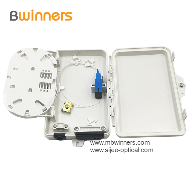
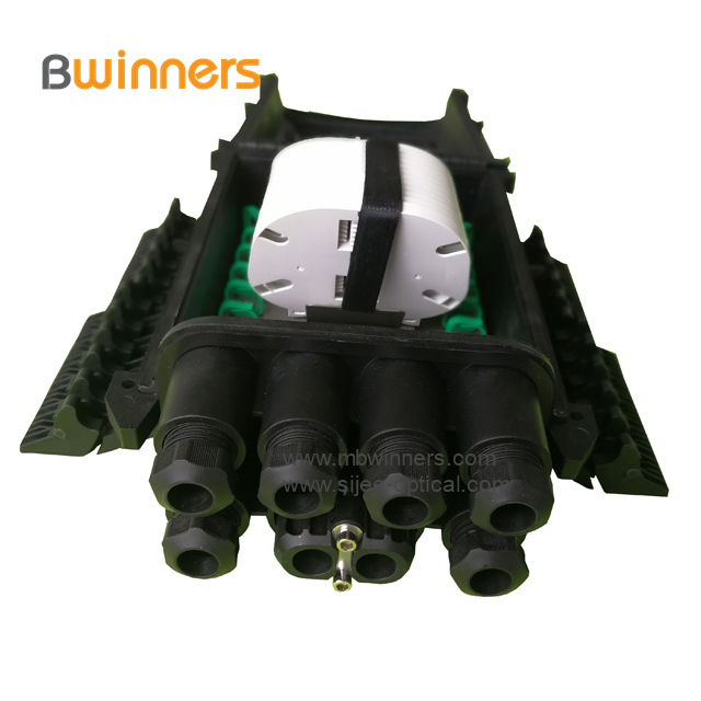
Fiber Optic Distribution Box / Fiber Splitter Box is used as a termination point for the feeder cable to connect with drop cable. The fiber splicing, splitting, distribution can be done in this box, and meanwhile it provides solid protection and management for the FTTX network building.
Material: PC+ABS,wet-proof, water-proof, dust-proof, anti-aging, protection grade is IP65.
Small Volume, For Indoor/Outdoor application. Compact structure,convenient installation and maintenance.


Fiber Optical Distribution Box (Plastic)
Fiber Optical Distribution Box,Plastic Fiber Optical Distribution Box,Fiber Optic Distribution Box,Optical Distribution Boxes
Sijee Optical Communication Technology Co.,Ltd , https://www.sijee-optical.com