This paper introduces the GPS technology and analyzes the feasibility of automatic tracking of locomotive headlights. It focuses on how to use ARM microcontroller to control GPS receiver, realize the overall solution of locomotive headlights automatically rotating according to rail curvature, and use preemptive multitasking. Real-time embedded operating system μCOS-II realizes the software processing process of control.
This article refers to the address: http://
Key words GPS locomotive headlight automatic tracing μCOS-II
introduction
GPS (Global Positioning System), the full name of the "Navigation Satellite Time and Range Global Positioning System", is the US second-generation satellite navigation system shared by the US Army, the Air Force and the Air Force, which was authorized by the US Department of Defense in November 1973. Built in 1994, it has significant advantages such as all-weather, high precision, automation, high efficiency, fast speed and low cost. GPS consists of three parts: the space part, the ground monitoring part and the user receiver. The GPS receiver can calculate its latitude and longitude position and speed by receiving satellite signals to realize the functions of positioning navigation and timing. It has become the world's most widely used and most practical global precision timing, ranging, navigation and positioning system. . China's GPS technology is also applied in measurement, sea and air navigation, vehicle monitoring and dispatching, missile guidance, precision positioning, dynamic observation, time transmission, speed measurement and so on.
The first report on the application of GPS to railway trains was the cooperation of Burlington Northern and Rockwell in 1984. In the late 1980s, the ARES (Advanced Railroad Electronic System) system was developed, and GPS has been used as a national railway standard precise positioning system [1]. At present, European railways are strengthening the use of GPS technology, and set up differential stations along the corresponding lines to integrate with mobile communication technology to improve the ability of railways to pass [2, 3]. In China, the high-tech integrated RITS (railway intelligent transportation system) technology such as GPS, GIS, GSM and computer has successfully developed the railway "GPS security alarm system", which was first in China in August 2001. The special passenger transport project - Qinshen Passenger Railway Line is delivered for use. Therefore, the application of GPS real-time positioning technology on railway trains will become more and more popular, and the application of GPS in railway trains has broad prospects.
1 Feasibility analysis of automatic tracking of locomotive headlights
In China, the locomotive headlights are not rotatable and are fixed to the head of the locomotive. When the locomotive enters the curve, the direction in which the locomotive headlights illuminate is tangent to the rail line, that is, the locomotive headlights cannot always illuminate the centerline of the track. Therefore, the locomotive brings a safety hazard during high-speed driving at night.
The working principle of GPS positioning technology is that the GPS receiver selects four satellites with the best position from the 24 on-orbit satellites. The time signal sent by the satellite is like an accurate clock signal, thus calculating the radius distance of each satellite. The position and height of the locomotive are determined by the position of the satellite using the principle of triangulation. The GPS receiver has a positioning accuracy of less than 50m. If necessary, the accuracy of the post-optimization algorithm can be higher, and the positioning accuracy can reach 3m with DGPS technology. It can be seen that GPS technology is a high-precision positioning technology.
A railway differs from a highway in that a certain locomotive operates only on a fixed number of lines and at a certain time. By receiving the discrete positioning data through the control system equipped with the GPS receiver, the railway track passing by the locomotive can be simulated with high precision, and the starting position, the ending position and the radius of curvature of all the curves of the line are calculated. When the system obtains the above data, according to the algorithm and control instructions, the stepper motor can be controlled to drive the headlight so that it always shines on the railway centerline.
2 system overall solution
2.1 The hardware composition of the locomotive headlight automatic tracing system
The system uses an ARM core microcontroller as a control center, and the peripheral circuit is composed of a GPS receiver, an electrical control module, and a flash Memory Module. The hardware schematic is shown in Figure 1.
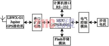
Figure 1 Schematic diagram of the locomotive headlight automatic tracing system hardware
2.1.1 System Central Processing Unit
Using Atmel's embedded CPU chip AT91R40008, this is a processor with ARM7TDMI core, rich peripheral interface, strong processing power, low power consumption, with two main buses: Advanced System Bus (ASB) and advanced The peripheral bus APB (Advanced Peripheral Bus). It is used to receive data from GPS receivers, perform line data extraction, line algorithm calculations, and generate control signals.
2.1.2 GPS receiver
In order to simplify the design of the whole system, the LBWXG1 Jupiter GPS receiver is adopted. The important parameters of this receiver are as follows: 12 satellites are tracked at the same time, the recapture time is less than 2.0s, the hot start time is less than 18s, and the cold start time is less than 120s. , speed accuracy is 0.1m / s, positioning accuracy is less than 15m (2dRMS), time accuracy is 1μs, acceleration limit is 4g, speed limit is 950m / s, data update rate is 1 / s, continuous update, can output NMEA Format or binary format data. This type of GPS receiver can meet the requirements of locomotive positioning accuracy and is used to receive satellite signals and transmit data to the central processing unit.
2.1.3 Electrical Control Module
It consists of a dedicated hardware circuit for receiving control information from the microprocessor and driving the stepper motor to control the headlights of the machine to rotate.
2.2 Working principle of locomotive headlight automatic tracing system
The entire system solution is divided into two phases.
The first stage is the GIS map generation stage. For a railway line that has never run the system, the line data file does not exist, and the GIS map must be generated by calling the line acquisition program in the system. First, the Jupiter GPS receiver receives the satellite signal through the GPS antenna, reads the RMC data, and calculates the position information of the locomotive mobile terminal, which is the longitude and latitude (Lat) data of the current position of the locomotive, and is (Lat, The form of Long) is stored in the memory. Then, the spline interpolation fitting algorithm is used to optimize the line data. Finally, repeat the above two steps, and finally form a discrete GIS map of the line, and save it in the system Flash as a system reference map.
The second phase is the system control phase. When the system generates the GIS reference map, the system control program can be run on the line to control the headlights of the locomotive to automatically track. When the locomotive is running, the Jupiter GPS receiver receives the satellite signal and sends it to the central control unit MCU through the RS232 serial port. The MCU reads the RMC data and extracts longitude, latitude (Lat) and velocity (Velocity) data from it. Then, according to the system position recognition algorithm, the geographical position closest to the GIS reference map data is identified, thereby determining whether the front of the locomotive enters a curve. If it enters, the radius of curvature of the curve and the number of rotation steps are solved to control the rotation of the stepping motor.
2.3 software composition of locomotive headlight automatic tracing system
2.3.1 Extraction of GPS data
Recently, almost all GPS manufacturers follow the NMEA-0183 version 2.01 communication standard format developed by the National Marine Electronics Association. All data information is encoded in ASCII format, and there are more than ten output statements, including GGA and GSA. GSV, RMC, BIT, RID, ZCH, etc. These positioning data statements not only give information on location, speed, time, etc., but also indicate local satellite reception. In the actual navigation, when the spatial positioning data of the GPS should be read, the data can be updated every few seconds as needed.
The Jupiter GPS receiver statement output follows the serial communication protocol. The data format is 8-bit data bit, 1-bit start bit, 1-bit stop bit, no parity, and the transmission rate can be selected as needed.
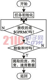
Figure 2 GPS data extraction flow chart
The locomotive headlight automatic tracing system requires high precision, high real-time and high reliability. Therefore, the update rate should be the system minimum setting value: 1s update once, and only the RMC data needs to be extracted during the extraction process, and the longitude is obtained from it. , latitude and speed data, the extraction process is shown in Figure 2. RMC data settings include information such as time, longitude, latitude, altitude, system status, speed, process, and date. The RMC data setting description is listed in Table 1. The data setting examples are as follows:
$GPRMC, 185203, A, 3339.7332, N, 11751.7598,
W, 0.000, 121.7, 160404, 13.8, E*55
Table 1 RMC data setting description 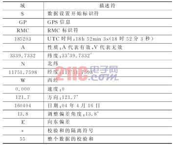
2.3.2 GIS map generation algorithm
The system uses spline interpolation. The spline interpolation method overcomes the weakness of the piecewise cubic Hermitian interpolation. It only needs to have two more boundary conditions than the Lagrange interpolation at the end of the interpolation interval, and the interpolation function can be constructed, and the interpolation function is interpolated. The second derivative of the node is continuous for better smoothness.
First, the line data uses a segmentation method. A division on a given interval [a, b]: a = x0 < x1 < L < xn = b. It is known that the function value of the function f(x) at the point xj is f(xj)=yj (j=0, 1, L, n), where x represents latitude and y represents longitude. Segmentation function
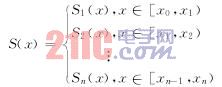
The function S(x) is the f(x) spline interpolation function, which satisfies the following conditions according to the spline interpolation function f(x):
1 Interpolation condition and function continuous condition, S(xj)=yj, S(xj+0)=S(xj-0);
The first derivative at 2 n-1 inner nodes is continuous, S'(xj+0)=S'(xj-0);
The second derivative of 3 n-1 inner nodes is continuous, S′′(xj+0)=S′′(xj-0);
4 natural boundary conditions, S′′(x0)=0, S′′(xn)=0. The piecewise function S(x) can be found, that is, the optimized trajectory curve.
Then, according to the piecewise function S(x), the points are uniformly taken over a given interval [a, b], generally ensuring that the distance between each adjacent two points is less than one-half of the GPS accuracy, forming the line Discrete GIS map database. Repeat this algorithm on different segments to calculate all segments to form a complete GIS reference map.
2.3.3 Microcontroller Control Process
The general flow chart of the locomotive headlight automatic tracing system software is shown in Figure 3.
The system control software is based on μCOSII embedded real-time operating system. The embedded operating system μCOSII is an open source multi-tasking micro-core RTOS with open source code. Its performance and security can compete with commercial products, and it is portable. Can be tailored, deprived and other advantages [4].
In the embedded operating system μCOSII, first initialize the system, open the timer, open the serial port interrupt, and perform the corresponding I/O settings. Then, load 2 main tasks. The task 1 serial port receiving program is responsible for receiving the RMC data sent by the Jupiter GPS receiver in real time, and extracting longitude, latitude (Lat) and velocity data, and sending it to task 2 by means of semaphore. The task 2 control algorithm program performs path comparison, curve judgment and rotation angle calculation, and the result is sent to the control command to drive the electric control module, thereby driving the stepping motor to rotate.
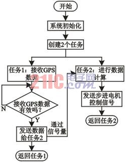
Figure 3 General flow chart of the locomotive headlight automatic tracing system software
Conclusion
The author has developed an experimental system, and proposed corresponding solutions for the two key problems of high positioning accuracy and fast response time. Through more than one year of trial operation, good experimental results have been achieved.
With the increasing maturity of GPS positioning technology, the positioning accuracy is increasing. In the near future, the GPS train positioning system, which is independent of the railway signal system, will play a major role in the safety of high-speed trains. Future GPS technology will have a lot to do on the railway.
SIMATIC S7-200, S7-300, S7-400, S7-1200, S7-1500, SIMATIC ET-200 Distributed I/O, SIMATIC WinAC, Siemens Process Control PCS7, Siemens SCADA WinCC, Operator Panels, Touch Panels, Industrial Networks: Profibus, Profinet and Modbus.
Control Concepts owns the software for all of these platforms so we are ready to go on service calls to troubleshoot your existing controls or program for new applications. We can assist you in migrating from older platforms such as S5 to S7.
Simatic C1 Modules
Simatic C1 Modules,Initializing Pulse Encoder,HMI Larger Smalcomparators
Xiamen The Anaswers Trade Co,.LTD , http://www.answersplc.com