FM transmitter circuit
figure 2:
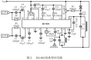
BA1404 is one of the few FM transmitting integrated circuits, which makes up for the shortcomings of designing FM circuits with discrete components in the past, and has the function of stereo modulation. Only a few external components can get a beautiful stereo FM signal. Therefore, it has important application value in FM stereo emission and wireless microwave. 1. The main features of BA1404 The main features of BA1404 are as follows: low voltage, low power consumption design, voltage between 1 ~ 3V, typical value is 1.25V, maximum power consumption 500mW, quiescent current is 3mA; stereo modulation, FM The modulation and RF amplification circuit are integrated on a chip; few peripheral components are required; the two-channel separation is high, with a typical value of 45dB; the input impedance is 540Ω (fin = 1kHz), and the input gain is 37dB (Vin = 0.5mV); The typical RF output voltage is 600mV. 2. Pin function and working principle BA1404 is mainly composed of pre-amplifier (AMP), stereo modulator (MPX), FM modulator and radio frequency amplifier. The stereo front stage is an audio amplifier with two channels. When the input is 0.5mV, the gain is as high as 37dB, and the bandwidth is 19kHz. If there is a component with a frequency higher than 19kHz in the input signal, a low-pass filter must be added to the input, otherwise the separation of the two channels will decrease. In the stereo modulation group, the 38kHz signal output by the oscillator is modulated in stereo. Usually an adjustable resistor is connected to pins 16 and 17 to obtain the best channel separation. The modulated signal synthesized by the stereo mixed signal (MPX output signal) and the pilot output signal (PILOT OUT) enters the RF oscillator through pin 12 and performs FM modulation on the carrier wave. The RF signal is amplified and the RF signal is output. The typical value of the RF signal is at Around 600mV. BA1404 also provides a reference voltage unit VREF. The designer can use this voltage signal to change the capacitance value of the external varactor diode, and then change the oscillation frequency of the carrier. Therefore, as long as the voltage division value of a resistor is controlled, the purpose of changing the transmission frequency can be achieved, which is a relatively unique design. 3. Typical application diagram is the typical application circuit of BA1404. In the figure, the left and right channels input audio signals into the BA1404 through a pre-emphasis circuit. The internal reference voltage is used to change the capacitance value of the varactor diode, thereby realizing the adjustment of the transmission frequency. Pay attention to the following points during design: (1) In order to make the frequency response of the transmitter and FM receiver match each other, a pre-emphasis network needs to be added at the input end, and its time coefficient is 50 μs. (2) At the 13th and 14th feet, when the stereo mixed signal and the pilot signal output by the stereo modulator are combined, the separation of the stereo channels may be deteriorated, so you must pay attention to the values ​​of the peripheral components of the 12, 13, and 14th feet. (3) If the output frequency range of the OSC oscillation network is within 76-108MHz, it can be wound around 2.5 turns with a 0.5mm enameled wire on a 5mm iron core, so that the capacitance value of C11 is 47pF. The same should be true for the RF matching network on pin 7. (4) In order to simplify the application, the following measures can be taken: leave feet 16 and 17 floating. Because the channel separation has been ensured within the integrated block, the adjustable resistor is only for optimization. There is no need to fine-tune the transmission frequency of the varactor diode, and a short circuit is directly at the varactor tube, so that R3 and D1 can be omitted. The RF matching network on pin 7 can be omitted and directly connected to VCC. The emission range of the BA1404 application circuit shown in the figure can reach hundreds of meters. If you want to increase its emission distance, you can add an RF amplifier to the RF output, you can use discrete components, or you can directly choose RF from MAXIM. Power amplifier circuit MAX2611 or MAX2650, they are suitable for matching with BA1404.
If you are new to the concept of using an electric kettle, you might be overwhelmed by the variety of electric kettles that are displayed on the store shelves and have difficulty deciding which one would be the best to suit your individual needs or desires. This introduction will give you some basic information about some of the features that are available on various types of electric kettles so that you can make a more informed decision when choosing one for use in your home.
Features:
Spend few minutes to boil : After 5 minutes, hot water will finish for you to drink.
3 protection functions : The on/off button is on the handle, making it easy to turn the kettle off when you pick it up. A concealed heating unit reduces the amount of buildup in the kettle.
It will be a problem when you forget to close the button.Once the water boils the kettle shuts itself off.Do not have to worry about damaging it by letting it run dry. When water runs dry,It will cut the electric by itself.
Multiple Cups: Water can be loaded to 1.8Liter.
Materials :
Food grade stainless steel, more healthy and hygienic. PP handle wieh heat insulation material provides scald resistance. Durable controller performance with 360 degree rotation cordless base design.
OEM & ODM service : Try best to support you during production and provide better after-sales service.Enhance your brand popularity.
Application:
Make a cup of tea.
Boil eggs.
Cook noodles.
Electric Water Kettle
Electric Water Kettle,Aluminium Electric Water Kettle,Mini Electric Water Kettle,Stainless Steel Electric Water Kettle
Guangzhou Taipeng Electrical Appliances Technology CO., LTD. , https://www.kettles.pl